I used 3 per rail, so about 7200uF total. No magic numbers here, wanted to get as much decoupling, as close as possible. It becomes an exercise in working out the physical positioning to make it happen ...Suggestions on the decouple value at the board .....?
Frank
Using inventory , which means 80K/2 per channel and then decoupled at board , remote transformer , Not into the million caps to achieve the same value , never liked the sound of the ones i have heard in the past ...
Suggestions on the decouple value at the board .....?
If you are not using an array, then you will still need decoupling caps at the DEVICE, which is a different set of caps than any that are just for the board.
The lower audio frequencies are not usually a big worry, when thinking about decoupling caps. But the higher audio frequencies definitely can be affected, which can ruin stuff that is dependent on accurate timing, such as phase angles of Fourier components, which could blur the details that probably play a large part in soundstage image perception.
Basically, as you get closer and closer to the point of load, you can have: the PSU itself (not including its caps), PSU's inductance, the PSU's caps, the rails' inductances, the board caps, the traces' inductances, the decoupling caps right at the point of load, the device pins' and lead-frame's inductances, and any on-device capacitance, then the actual point of load.
The distance from the point of load determines what frequencies each of those Cs and Ls can affect, mainly because of the inductance and the self-inductance associated with the lengths of conductors.
The pattern of capacitance, inductance, capacitance, inductance, ... is not accidental. The inductances make the impedance versus frequency plot slope upward and the capacitances try to bring it back down, hopefully keeping it under the maximum "target impedance" that we want the point of load to see, which is simply the p-p ripple we decide is acceptable, divided by the current draw that causes it.
For each set of caps mentioned above, you can either set a cap value and then calculate the maximum distance from the point of load that they could be, to still keep the target impedance within range, or, you can pick a distance and calculate the minimum capacitance required, to still stay under the target impedance at the point of load.
Either way, the common enemy is the inductance, due to the length of the conductors.
More-directly to your question, For the "right-at-the-output-device" decoupling caps, you will want to make sure that they can supply ALL of the current for the highest slew-rate that the device is capable of ever achieving, while assuming that it slews over the maximum-possible voltage range at that slew-rate. And that should NOT be limited to audio-frequency slew rates. That will give the MINIMUM VALUE of the decoupling capacitance. The reason it's just the lower bound is because we are only looking at the FASTEST slew rate. Even small-value caps can produce very large currents for a SHORT time. But slower slew rates would need LARGER caps.
That's easy to calculate and I'll do it in a second. But NOTE that you then MUST calculate how much conductor length, i.e. inductance, there can be, between the decoupling caps and the point of load, so that when that massive slewing occurs, the ripple voltage it creates does not exceed your chosen target, which is the same as saying that the target impedance ceiling is not broken.
Because of the inductance that comes with conductor length, we have to first find out what minimum cap value is needed, at up to what distance from the point of load, to be able to supply the fastest and largest slewing event.
For slightly-lower slew-rates, we would actually need a LARGER capacitance, but it could be a little farther away from the point of load, because even though being farther away will incur more delay due to more inductance and more ripple due to more inductance (V = L di/dt), the slew rate is slower so more delay can be tolerated, and since slew rate IS dv/dt a lower slew rate makes less voltage across any given inductance.
Interestingly, we can now see that if we increased the inductance (by increasing cap's distance from load) at exactly the same rate at which we lowered the slew rate (for which we increase the cap's value), then the p-p ripple would stay constant. So, when a target impedance is able to be implemented (which is not always the case), there is apparently a continuum of equivalent solutions for the cap value and the caps's distance from the point of load, which we can scout along until we find a location and size combination that is practical to implement!
In reality, the inductance limits the frequency that can be decoupled, no matter what capacitance we might try to use, so we need to have capacitances every so often, in increasing values as the distance from the load (inductance) increases, so that all of the frequencies are covered well-enough, which is just what we do, with PSU caps, board caps, and then decoupling caps right at the power devices.
We might also then guess that it's not a good idea to make jumps in capacitances, between those points, that are "too large". I would guess that each stage should be within a factor of 10 or 1/10th of the next or previous stage's capacitance. Otherwise, the anti-resonances that always appear between parallel capaitances, in the frequency-domain (network analyzer) plots of impedance, might have a big-enough frequency span to peak above our target impedance.
MINIMUM DECOUPLING CAPACITANCE at MAXIMUM SLEW RATE and EXTENT:
Ideal capacitor: i = C dv/dt
From my post at http://www.diyaudio.com/forums/chip...-rms-power-5-watt-chip-amp-5.html#post3317518 :
C ≥ (1/2)∙(Δi∙Δt ) / (Δv - (ESR∙Δi))
which gives the minimum capacitance required such that when the current ramps linearly and changes by Δi Amps in Δt seconds, the voltage across the capacitance (typically, the power rail voltage) won't dip by more than your choice of Δv.
NOTICE that if the denominator of that equation gets close to zero, the C value would get extremely large. The denominator would go to zero when Δv - (ESR∙Δi) = 0, i.e. Δv/Δi = ESR. BUT Δv/Δi is none other than our "target impedance"!
In plain English, that means that if the ESR is not a lot lower than our desired target impedance, then we would need excessive values of capacitance.
EXAMPLE:
40 Volts per microsecond into 4 Ohms, for one rail in a system that can push 200 Watts into 4 Ohms or 100 Watts into 8 Ohms:
Find the peak current. The peak output voltage would, coincidentally, be 40 Volts, since V_peak = sqrt(2*R_load*Power_rms).
Swinging from 0 Volts to 40 Volts across 4 Ohms would mean that the current would swing from 0 Amps to 40/4 = 10 Amps. And that would happen in one microsecond.
Since we don't yet know the capacitance, we don't know the ESR. So we'll leave it out and see what C value we get and then go re-calculate it with an estimated ESR (and we might then have to iterate using the ESR of the new C value, until the results stop changing by very much).
C ≥ (1/2)∙(Δi∙Δt ) / Δv (without ESR, tempoarily)
C ≥ (1/2)∙(10 Amps∙1 us ) / Δv
C ≥ 5 uF / Δv
If we choose Δv = 1 volt maximum ripple peak-to-peak, C would need to be at least 5 uF.
We should be able to get a very low ESR for 5 uF, especially if we parallel three or more small-ish film caps. So 10*ESR should be able to be much less than our 1-Volt Δv, so we shouldn't need to re-calculate the C equation, in this case.
NOW, we MUST check to see if it is even POSSIBLE to mount the capacitor(s) in order to get a low-enough inductance that the ripple doesn't go over our chosen value, 1 Volt in this case.
For inductances:
V = L di/dt
We have di/dt = 10 Amps / 1 us = 10 / 0.000001 A/us = 10000000 A/sec, and need the resulting V (our Δv) to be <= 1 Volt. So
1 = L x 10000000
L = 1/10000000 = 0.000000100 = 100 nH
We could estimate that allowing 100 nH allows a round-trip distance of 100 mm. So (whew!) that should be able to be implemented, although it will be more difficult than it might seem. The four connections, each cap lead and each device lead (power and ground), need to total less than 50 mm, MINUS the cap's lead spacing, minus the device's additional lead lengths (going all the way inside to the silicon).
SECOND METHOD:
We should also check the required capacitance value another way, and choose the larger of the two (i.e. either the one above or the following one, whichever is larger):
Since the magnitude of the impedance of a capacitance is Z = 1 / (2 Pi f C), we can solve for C for a given Z (Ohms) and f as:
C = 1 / (2 Pi f Z)
The frequency that is equivalent to the example rise time of 1 us is:
f = 1 / ( π ∙ trise )
f = 318 kHz
So we must stay within our target impedance limit up to at least 318 kHz.
We can calculate that in order to maintain our target impedance of Δv/Δi, we would need a total capacitance of at least
C >= 1 / (2 ∙ π ∙ f ∙ Δv/Δi)
= 1 / (2 ∙ 3.14 ∙ 318000 ∙ (1/10))
= 5 uF
Never mind. If we substitute the f(trise) equation into this C equation, it becomes, exactly, the earlier original C equation.
----
OK. THAT example turned out to look implementable, with a target impedance of Δv/Δi = 1 / 10 = 100 mOhms, which corresponded to 2.5% ripple.
EXAMPLE 2:
But that assumed we could have a whole VOLT of ripple. What if we had wanted a target impedance of 20 mOhms (0.5% ripple), in order to get 0.2 Volt ripple?
That would mean a Δv = 0.2 Volt, which would mean
C ≥ 25 uF
which would mean a much larger ESR (unless we used much larger (or many more) paralleled film caps). So that C value would likely have to be increased, a whole lot, when we re-calculated with the original equation that inckudes ESR, unless our ESR could somehow be a lot less than 20 mOhms. We would almost be forced to use several paralleedl caps, to get the ESR that low. But that takes a lot more space on the board.
At the same time, the maximum allowable inductance in the decoupling network is now 20 nH instead of 100 nH. That's only roughly 20 mm, including the cap's lead spacing plus all of the conductors to and from the device's silicon. And that's the absolute maximum.
It's looking close to impossible to implement, at least with a standard through-hole DIY configuration, unless we used lots of parallel caps, arrayed on unbroken copper planes, with extremely short and fat connections between the planes and the output devices.
Hmmm ... sounds about right ...It's looking close to impossible to implement, at least with a standard through-hole DIY configuration, unless we used lots of parallel caps, arrayed on unbroken copper planes, with extremely short and fat connections between the planes and the output devices.
")
Frank
After all of THAT, we don't have a proper decoupling capacitance, yet. The 5 uF of film caps would only cover the highest frequencies needed, as far as we know. Lower frequencies, with the equivalent of slower slew rates, would require larger caps.
We could do a lot of math, or simulations, but as we have already seen, really-good specs can result in impossible implementation requirements.
We COULD laboriously calculate until we find what should work, by trying many different target impedances, or by trying many different distances from the load, or many different capacitances, until we think we have good-enough specs for all three and might be able to implement them.
OR, we could start by trying to do the PCB layout, and just see how much capacitance can be mounted, and how close to the point of load it could be, and work our way outword with larger and larger C values, mounted as densely as is practical. And then we could calculate, just once (and maybe with much-more-accurate inductance estimates), and see what maximum slew rate and maximum ripple and minimum impedance we were able to attain. (OR, if we really think that we couldn't ever do any better, and could never get any more capacitance mounted closer or with with lower inductance, and the specs will never satisfy us anyway, then there's no need to even calculate. Just build it, and then maybe measure it.
For the second approach, we might put three or hopefully more film caps (probably using the largst value available in whatever case size is small-enough) as close to the device pins as we can possibly get them, with at least 5 uF but hopefully more, and hopefully with much less than the 100 nH of maximum inductance we calculated. Then add another "layer" of caps, slightly farther away, probably using 47uF to 220 uF electrolytics, as many as will fit. THEN we could move out farther and put some larger electros, although I would always want to use multiple smaller paralleled caps instead of one or two larger ones, at each stage. And always use as much copper as possible, to lower the inductance.
BUT, of course, FIRST, we should have calculated the maximum peak-to-peak ripple voltage that we could tolerate, starting from PSRR.
Last edited:
I like that ... the short answer, and, the loooong answer ...
Just kiddin' ...
Frank
YOU actually READ all of that?!
I just make it up
as I go along,
and then follow where it leads.
So it could be wrong.
Or maybe it's MORE like...
singing a song...
that goes on too long...
so everybody leaves.
I used to read [memorize?] the Motorola power supply design guide books - no longer on hand - but 1000uf per amp sticks in my head as a general rule of thumb for a basic power supply - as a design trade-off for ripple & cost.
Rather than go overboard on trying to find a XX,000 uf cap [FOR ripple reduction], why not use a floating cap multiplier?
Rather than go overboard on trying to find a XX,000 uf cap [FOR ripple reduction], why not use a floating cap multiplier?
Poor, poor, a.wayne -- now look at what you've gone and done, Tom ...For the second approach, we might put three or hopefully more film caps (probably using the largst value available in whatever case size is small-enough) as close to the device pins as we can possibly get them, with at least 5 uF but hopefully more, and hopefully with much less than the 100 nH of maximum inductance we calculated.
,As regards film caps, back when I did this fella, many years ago, it didn't make sense to add them into the mix, the benefits were not there from a theoretical POV. And the amp didn't seem to suffer from not including them. Which is not saying that there may not be audible impact if one were to use the very latest and greatest parts -- something to play with for someone ...
Overall, the biggest benefit of my approach was to give the chip amp the sense of being "unburstable", no restriction on dynamics. Which was due to the effectively huge size of the capacitor bank ...
Frank
The capacitor charge/discharge is given by the relation
1Farad changes by 1Volt when 1Ampere is drawn for 1second.
From this you can examine any capacitor voltage change for any current over a specified time period.
eg
1uF 1V 1A 1us
or
100nF 1V 1A 100ns
or
100nF 1V 10A 10ns
Just to remind you what that means.
using a 100nF decoupling cap, you can draw 10A from it for a period of 10nanoseconds and the charge will drop by 1volt.
That would be your HF decoupling.
Now do the same for the MF decoupling and for the LF decoupling.
The difference between the HF & MF & LF decoupling is the Length (nanoHenries) of the route around the circuit
Ripple reduction is secondary. It's more about being able to provide current accurately on demand.
perhaps this thread was hijacked, but I was restricting my comments to caps and ripple. You MIGHT have to go all the way back to the circuit breaker to "provide current accurately..". Maybe start a new thread?
All of what you have mentioned has been discussed in ten different ways, here, already.
the pot calling the kettle black?
perhaps this thread was hijacked, but I was restricting my comments to caps and ripple. You MIGHT have to go all the way back to the circuit breaker to "provide current accurately..". Maybe start a new thread?
the pot calling the kettle black?
Please, here is a clue:
I have read this entire thread. I suggest that you do the same, so that your contributions can be relevant.
Hey Nico! Remember your VERY FIRST post, here? (Hint: It's Post #1.) You said:
"...one arrives at a reservoir capacitance of 80,000 uF."
Well looky there! It only took 1708 posts and about 6 1/2 months to get to "...giving C >= 83577 uF",
which is just a few screens back from here, at:
http://www.diyaudio.com/forums/power-supplies/216409-power-supply-resevoir-size-171.html#post3349466
I want to thank you, my friend, for putting up with me, in this thread. We have been through a lot, together, here, and have learned so much; all of us.
"The PSU CURRENT IS the audio signal, which almost all comes directly from the caps!"
Last edited:
Well put .Hey Nico! Remember your VERY FIRST post, here? (Hint: It's Post #1.) You said:
"...one arrives at a reservoir capacitance of 80,000 uF."
Well looky there! It only took 1708 posts and about 6 1/2 months to get to "...giving C >= 83577 uF",
which is just a few screens back from here, at:
http://www.diyaudio.com/forums/power-supplies/216409-power-supply-resevoir-size-171.html#post3349466
I want to thank you, my friend, for putting up with me, in this thread. We have been through a lot, together, here, and have learned so much; all of us.
"The PSU CURRENT IS the audio signal, which almost all comes directly from the caps!"
Have a look at Rubycon ZL range - that's showing 330uF/50V in 10mm with a max 100kHz impedance of 28mohm. In my limited experience of extreme paralleling of caps, I found going above 330uF to be problematic in that the self-resonant freq comes down a bit too low for comfort. I doubt when paralleling 100 caps that the high frequency ESR is going to be limited by the caps' ESR, more likely the interconnections.
Still thinking about the caps needed for the 10x10 (or so) array.
Maybe terminology is getting mixed up or maybe I am under some misconception. The self-resonant frequency is usually a GOOD place to be. It's where the minimum impedance is. It's the frequency at which a cap can most-quickly supply the most current.
Basically, we want a very low impedance, everywhere, if possible. But if there's a band of lowest impedance, it seems like we would want that band to lie across the audio band, and at least across the bass portion of the audio band, if we couldn't have it all.
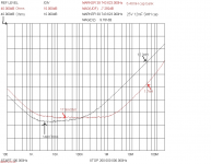
Attached is a plot of the impedance of Terry Given's 10x10 array of 1000 uF caps, on a 1.6mm-thick (instead of the desired 1mm, or less) PCB. The plot came from his HP 3577A analyzer (capable of 5 Hz to 200 MHz).
I would have thought that the cap array's impedance would be much lower than it is, at the lower frequencies. The 12.5 mF cap he compared it to looks lower, there. However, the 12.5mF cap doesn't include any connection wiring, whereas the cap array includes all of that already.
At any rate, the array's flat, lowest-impedance region appears to extend from somewhere between 2 and 5 kHz up to about 1 Mhz. (It does very well at the high frequencies.)
I think that, ideally, the lowest-impedance band should extend another two octaves lower, so that it includes down to somewhere in the 20-50 Hz region at its lowest-impedance level.
Would that mean using larger cap values or more total capacitance? Would it help to put caps on both sides of the pcb, to decrease the total PCB path length? (I realize that just getting 1/wC down to 0.02 at 20 Hz would require about 400000 uF. Is that what we would need?)
Then we see what Klaus got, here:
http://www.diyaudio.com/forums/powe...work-analyser-measurements-4.html#post3331935
Now I am scratching my head.
Suggestions?
Attachments
Last edited:
Ah, brings back memories ... how many times have I stared at curves like this ...Basically, we want a very low impedance, everywhere, if possible. But if there's a band of lowest impedance, it seems like we would want that band to lie across the audio band, and at least across the bass portion of the audio band, if we couldn't have it all.
...
Would that mean using larger cap values or more total capacitance? Would it help to put caps on both sides of the pcb, to decrease the total PCB path length? (I realize that just getting 1/wC down to 0.02 at 20 Hz would require about 400000 uF. Is that what we would need?)
?
Easiest way of getting that nice, low impedance in the audio band is to use regulation, otherwise, bigger, meatier and rough and ready electro's will be needed. The latter can be as low quality as you like, what you want is capacity, capacity, capacity, the most you can get for your money. I would aim for better than 1 m.ohm over the whole audio band, and try to maintain that up to 100-200khz. This is where you use your best quality electro's, heavily paralleled, short paths to the point needed. Once past that frequency, heading towards the MHz it starts becoming a real struggle, absolutely everything has to be just right, otherwise you're just wasting your money. You worry about millimetres of conductor, fight to reduce every nH ... and it may not actually be worth it ...

Frank
Thanks, Frank. I'm not really worried as much about the higher MHz range; only up to the reciprocal of Pi times the fastest rise-time.
But I just realized that I've not thought that through. For example, an amp that can do 40 V/us = 5 A/us could do 1 A in 1/5th μs, or 0.1 A in 1/50th μs, and so on. Where do I draw the line on that?! Wait, I might be getting it...
Z_target (max) = Δv_max / Δi , for any Δi, BUT, we pick a single Δv_max.
Before, I only looked at the worst-case full-range transient, like the 5A / μs, and made sure that it wouldn't generate more than a Δv_max glitch in the power rail voltage (i.e. the voltage across the decoupling cap).
But 0.1 A, with the same maximum di/dt (based on max slew rate), would be done a lot sooner, giving a much faster rise time (0.02 μs, for a 5A/μs max slew rate, for example), which would translate into a much higher equivalent frequency, 1/(π 0.02μ) = 15.9 MHz.
BUT, it's only 0.1 A and yet it's still allowed to produce the same Δv_max as 5 Amps was. So the Z_target at 15.9 MHz is allowed to be Δv_max/0.1, which is 50 TIMES higher than the Δv_max/5 that it had to be for the 5 Amp rise in 1 μs, which corresponded to 1/(π 1μ) = 318 kHz.
Cool. Now I have a way to get the high-frequency part of the Z_target impedance curve.
I was "assuming", without really thinking about it, that Z_target was a constant from say 20 Hz to 318 kHz, and then didn't matter, except that we would want it as low as possible, and with no impedance peaks, so that no HF resonances would get too excited.
So now I'm wondering, above what frequency DOES the z_target curve cease to matter?
Does the stuff above really mean that if the PSU impedance at 15.9 MHz is too high, a 0.1 Amp or smaller transient cannot be produced at the maximum slew rate without causing a rail disturbance that is greater than the Δv_max that dictated that impedance at that frequency?
Well, never mind that, for now. The amplifier will be limited in its frequency response, probably well before that point. We just want to make sure that it's not unable to correct whatever needs to be corrected, which it does eventually become unable to do, above some frequency.
Anyay, as I implied, I am thinking more about the lower frequencies, right now. What is a reasonable impedance to aim for, down to 20 Hz?
Frank, you mention 1 mOhm; 0.001 Ohm. For the example with 5A/μs slew rate and 0-5A range, that would mean a worst-case Δv_max = 0.005 Volt.
Ignoring ESR, which, at very low frequencies, would be swamped by the capacitance when paralleling lots of electrolytic caps, anyway, to get 0.001 Ohm at 20 Hz we would need
C = 1 / (2∙π∙20∙0.001) = 7.96 million μF; almost 8 Farads!
I'm just not going there. But the question is, how far WILL I go? And, WHY?
With 100000 μF (from the 10x10 1000 μF), we would have Z = 80 mOhms, at 20 Hz. That means that 0.080 = Δv_max / Δi , which for our example 100-Watt amp with the 5-Amp swing, would give Δv_max = 5(0.080) = 0.4 Volt, at 20 Hz, which would be "1% ripple" at the maximum rated output power.
PSRR is usually very good at lower frequencies, though. So as long as we have enough capacitance to produce the demanded current, then how much ripple we create shouldn't matter much, within reason.
I guess we would need a plot of PSRR vs frequency, to be able to create a plot of acceptable ripple amplitude vs frequency, for a chosen maximum distortion level (or something like that).
But we also know that above some relatively-low frequency, the impedance will be almost identical to the ESR divided by the number of caps, which will be some small fraction of 1 mOhm, for 100 large-value caps in parallel, with unbroken copper power and ground planes. So we only have to worry about the low and low-mid frequencies, maybe, where the capacitance's impedance starts to dominate over the ESR.
Xc = 1 / (2∙π∙f∙C) .
For C = 100000 μF, that becomes Xc = 1.59 / f .
For C = 220000 μF, we get Xc = 0.723 / f .
At 100 Hz, we'd have 15.9 mOhms with 100kμF, or 7.23 mOhms with 220kμF, giving 0.0795 V worst-case ripple amplitude for a 100 Hz 100-Watt sine with 100kμF, or 0.0362 V worst-case ripple for a 100 Hz 100-Watt sine with 220kμF, for example.
We would just need to know what effect it might have, and how low the ripple needs to be at each frequency, and then we could decide how much capacitance was actually needed. Again, the PSRR might tell us those answers. I'll have to go investigate PSRR and ripple-induced distortion, now, I suppose. DF96, Frank, anyone? Any ideas about that?
-------------------------------
I happened to run across the following paper which some might find interesting or enlightening:
www.illinoiscapacitor.com/pdf/Papers/low_ESR_fact_or_fiction.pdf
- Tom
Last edited:
Hey Nico! Remember your VERY FIRST post, here? (Hint: It's Post #1.) You said:
"...one arrives at a reservoir capacitance of 80,000 uF."
What do you know, and that was sucking my left thumb only
Tom, your work on this thread remains exemplary.
- Status
- This old topic is closed. If you want to reopen this topic, contact a moderator using the "Report Post" button.
- Home
- Amplifiers
- Power Supplies
- Power Supply Resevoir Size