We don't know the specifics of the instrument, but it would be interesting to know how or even if manufacturers determine HF capacitance alone. Apart from the known heavy dependence on frequency, there are a number of tech forum comments pointing to the LCR meter and and its limitations in resolving mixed L,C, R properties of the DUT. This may agree with your findings..........
50Hz 9,535uF
1kHz 8,035uF
10kHz 1,530uF
20kHz 495uF
Anyone else come across this? I tried a couple of other brands (Rubycon, Elna), similar results. The capacitance is down to 5% of its marked value at 20kHz, seemingly due to internal inductance which, in turn varies with frequency. I calculate about 0.5uH @ 1kHz down to 120nH at 20kHz.
It may not be an issue, but don't elcos also require a DC bias to achieve full ratings?
As far as I'm aware, my LCR (Tonghui TH2817B) determines the overall impedance by measuring the resistive (in phase) component together with the reactive (quadrature) component. Its probably using a standard chipset not too dissimilar to this one: http://www.cyrustek.com.tw/spec/ES51920.pdf
I've since played around some more and found that the 4 wire probe set I was using doesn't give the most consistent results, so I've cross-checked with a more traditional static test fixture. The readings were similar at lower freqs but this refused to give a capacitance reading at 10kHz measurement frequency, implying the 10mF cap looks to be near as damn it a short. At 20kHz its overall inductive, reading a negative capacitance value
I'm not sure if DC bias is required, however my meter operates with a predictable polarity as the leads are clearly marked +(red) and -(black).
This capacitance variation anomaly sounds like a methodology problem.
What if you select a frequency and appropriate resistor for the F-3dB frequency and simply measure the voltage across the cap and the resistor?
Then change the frequency and select a new appropriate resistor value and measure again.
Yes the Capacitive impedance at 20kHz is very low. The series resistor must also be very low for the two measured voltages to be near enough equal.
That low value of HF impedance is confirming that the capacitance is still high at the 20kHz test frequency.
Last edited:
Reduced capacitance at higher frequencies may be a consequence of the deep foil etching used to make modern small-size big-value caps. The reduction may be as much due to the resistance of the foil as its inductance. Interestingly, this could mean that new electrolytics are worse than an old-but-fresh original component (if such a thing could be found).
In many cases it doesn't really matter, provided that the actual net impedance remains low. You could argue that if 10000uF is required at 20Hz, then only 10uF is required at 20kHz to do the same job. I know it's not quite that simple, but it may mean that if 500uF at 20kHz is all the cap can deliver then it is still plenty enough to do the job.
In many cases it doesn't really matter, provided that the actual net impedance remains low. You could argue that if 10000uF is required at 20Hz, then only 10uF is required at 20kHz to do the same job. I know it's not quite that simple, but it may mean that if 500uF at 20kHz is all the cap can deliver then it is still plenty enough to do the job.
Reduced capacitance at higher frequencies may be a consequence of the deep foil etching used to make modern small-size big-value caps. The reduction may be as much due to the resistance of the foil as its inductance.
Wouldn't an increase in foil resistance though show as a loss term - it would contribute to ESR no? The LCR meter measures ESR and this reduces with increasing frequency - I think that's one reason why cap manufacturers show ESR at a measurement frequency of 100kHz.
In terms of current delivery I agree with your reasoning that at higher freqs, less capacitance is needed, all other things being equal. However amp PSRRs generally reduce at 20dB/decade so in PSRR terms we'd need to maintain the same rail capacitance above the PSRR corner freq to have an error term (arising from the finite PSRR) which was flat with frequency.
@Andrew - yes the resistor has a very low value in your suggestion. Take 10mF and a -3dB freq of 10kHz, it gives R = 1.6mohm by my reckoning. This is way below the ESR of the cap.
Last edited:
Not necessarily. What can happen is that you get, in effect, a whole set of tiny capacitors wired in parallel but with series resistors, and a capacitor with little or not resistance. As the capacitive reactance drops with increasing frequency all the tiny caps effectively disappear and you just get the resistance in parallel with the main cap. But that too has a low reactance so it swamps the resistance so you don't see it.abraxalito said:Wouldn't an increase in foil resistance though show as a loss term - it would contribute to ESR no?
Something to try if you have never done it before is to explore, either by calculation simulation or measurement, the effect of series to parallel conversions. e.g. put a low value resistor in series with a cap, then another cap in parallel with that. See how the toal impedance varies with frequency, and where the effective resistance peaks. Even a simple circuit like this has counter-intuitive behaviour. The resistance has most effect at mid-frequencies, not high or low frequencies. You can even find values which mean that increasing the internal resistor means the external measured resistance goes down!
Yes, good point. I hadn't thought of that. However, it is relatively easy to add a bit more decoupling and improve PSRR.However amp PSRRs generally reduce at 20dB/decade so in PSRR terms we'd need to maintain the same rail capacitance above the PSRR corner freq to have an error term (arising from the finite PSRR) which was flat with frequency.
can you use this and DF's next post to determine, even if only approximately, what the relative reactances are of the capacitance and esr?.........Take 10mF and a -3dB freq of 10kHz, it gives R = 1.6mohm by my reckoning. This is way below the ESR of the cap.
Are we into Wheatstone territory?
Is it Member Conrad that has a website showing how to measure capacitance and esr etc?
Last edited:
However, it is relatively easy to add a bit more decoupling and improve PSRR.
Perhaps you're thinking of a discrete component amp where the signal stages can have series Rs. I was thinking of a typical chipamp where there's only one pair of pins for power, doing duty for both signal and output stages. Adding more decoupling is just making the main reservoir cap bigger...
No.Adding more decoupling is just making the main reservoir cap bigger...
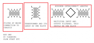
locating the HF decoupling and the MF decoupling correctly such that each can perform as expected and the LF decoupling (= smoothing?) can be almost anywhere. LF decoupling can and should be right next to the rectifier/s not necessarily on the PCB.
Here I have to make a confession - I can't quite see the point of local (HF) decoupling when the current loop being decoupled is much larger than the PCB itself. Perhaps I'm missing something though... I'd always thought that local decoupling was to keep the current loop small, but with an audio chipamp we've a relatively huge loop area compared to the circuit under consideration. Even if we assume we're decoupling to star earth and the speaker return comes back there too, that's not generally on the amp PCB so there's appreciable inductance in the wire back to star ground. That inductance seems to me to be in series with our HF decoupling cap rather nullifying its moniker as 'HF decoupler' no?
The decoupling must connect the output pin to both power pins.
For HF this route must be a very short route.
This requires the Zobel to be mounted on the output pin and the HF decoupling to be mounted on the power pins. Then the remote ends of all three must be connected together with the shortest possible route lengths. This works for discrete and for chipamps.
Gootee had a good analogy a long while back and he has repeated it a few times for those that were not listening.
Think of the amplifier being fed by a "battery" that consists of only the HF decoupling capacitor.
Imagine all the other supplies to be removed. Now trace out the route that the current flows from our tiny "battery" in through the power pin, out through the output pin, into the HF load (Zobel) and back to the "battery". That is the route that MUST be minimised. Repeat this virtual "battery" for the other polarity capacitor.
Then move on to consider the MF decoupling, but one can now relax the restrictions on "Route Lengths" due to tolerance of slightly higher inductances in the traces and leadouts.
Notice that Main Audio Ground has not entered into any of the MF, nor HF routes !!!!!!!
Main Audio Ground should only see Audio Frequencies, if the correct decoupling has been properly located.
Last edited:
Ah - I'd forgotten about the Zobel network, thanks - that makes it more interesting still but at least I now see one aspect of what I was missing before.
Seems to me that the Zobel, being as it is an RC (i.e. an AC coupled resistor) can equally well be to one or other, or even to both of the supplies rather than to ground. The 'both' case being handled by two caps (rather than the usual one) acting as rail splitters and the cold end of R going to the junction of them. ISTM this case will offer the lowest inductance seeing as the current is always sourced from one or other of the rails. Those two rail splitting caps can also do duty as HF decouplers can they not? In this case they've just created a local 'ground' (more precisely an average of the +/- rail voltages) which has no need to be returned to the star earth.
This has all been assuming the current to the speaker doesn't need to be considered. Does it though?
I thought that's what is described in post 1551 ?
The local decoupling ground right between the Power Pins and the Zobel connecting the output pin to this local decoupling ground. Isn't that what I said?
But the clever bit is the simplification offered by Gootee to "see" the caps as if they were "batteries" and these being the sole power/current supply.
The final bit is to connect the PCB Power Ground to the Main Audio Ground. Speaker current (Audio Signal) does not pass along this connection.
Last edited:
But in my notion, its not actually a ground because it has no electrical connection to ground. Ignore the label, just think of a Zobel network with two caps instead of one. Its actually saving one cap because in your described situation we have 3 caps - 2 decouplers (one to each rail) and 1 in the Zobel.
<edit> Agreed, Gootee's suggested visualization helps a lot.
<edit> Agreed, Gootee's suggested visualization helps a lot.
Last edited:
Small single rail application
For example 4700u||10u, -0-, 4700u, a 50/50 capdiv also serving as power supply reservoir:
That spot marked -0- (centerpoint of the capdiv) is the only speaker return on my little single rail radios. The speaker return is the only thing connected to the centerpoint of that capdiv. Offset was not a concern because it has an output cap anyway. Works great for a couple of watts. Totally removes treble errata that I was having trouble with previously. I wonder how? Works on several radios, including Zenith Circle of Sound clock radio. It was loud enough before, but holy cow!--it doubled! And, yes, clean treble too. The outcome is the same each time I've tried it.
Questions:
Why did that modification double the speaker output power?
Why did that modification clean up to treble so much?
Last edited:
With regard to capacitance changing with frequency, I note on a Rubycon technical document that they acknowledge a loss with increase in frequency, due a combination of the condition of the etched surface, properties of the film as a dielectric, properties of the electrolyte, and the nature of the construction of the capacitor: they show a 10uF, 50V unit being down by about 15% at 20kHz. But only by that much ...
At the higher frequencies the ESR and construction becomes everything for getting effective decoupling, the actual true value of capacitance becomes almost completely meaningless ...
It's easy to know where one end of the decoupling caps should go -- to the power pins -- but where to attach the other end? My take is that it should be the ground point that the feedback network sees, which should be electrically equivalent at all frequencies to the ground of the audio input.
Frank
- Status
- This old topic is closed. If you want to reopen this topic, contact a moderator using the "Report Post" button.
- Home
- Amplifiers
- Power Supplies
- Power Supply Resevoir Size