Daniel @ #1213
you are right re. the cap ESR, but as Frank points out above, ESR varies strongly with time, temperature and sock colour (among other factors). its a commonly used trick, but because of this variation its not a very robust one. look at an electrolytic ESR for example - good cap data sheets specify ESR at 20C and at -10C - this is because ESR rises sharply at low temperatures. this can (and does) cause stability and even startup problems with regulators that rely on the ESR*C zero for stability.
A much more robust, predictable method is to use very low ESR caps, then add your own series resistor to get the desired zero/damping. pay close attention to peak pulse power dissipation though - not all resistors are created equal.
This specifically includes wire-wound resistors - quality WW resistors pack the wound mandrel with potting material before placing it in the ceramic body & encapsulating it; cheap nasty WW resistors drop the wound mandrel into the ceramic body and cover over the hole. the result is plenty of air around the resistive element, which hugely decreases its peak power handling capability - I have seen pretty orange flashes of light coming from the resistive element when given a good thump, before the resistor fails. Vitrohm for example dont do this, but all the WW resistors I can get from hobbyist stores in NZ are made like this. you can check a WW resistor by smashing it open with a hammer, providing hours of entertainment and making a mess")
there are also some seriously good SMT resistors with astonishing peak pulse power ratings - Panasonic ERJP and Vishay CRCW-HP are awesome.
you are right re. the cap ESR, but as Frank points out above, ESR varies strongly with time, temperature and sock colour (among other factors). its a commonly used trick, but because of this variation its not a very robust one. look at an electrolytic ESR for example - good cap data sheets specify ESR at 20C and at -10C - this is because ESR rises sharply at low temperatures. this can (and does) cause stability and even startup problems with regulators that rely on the ESR*C zero for stability.
A much more robust, predictable method is to use very low ESR caps, then add your own series resistor to get the desired zero/damping. pay close attention to peak pulse power dissipation though - not all resistors are created equal.
This specifically includes wire-wound resistors - quality WW resistors pack the wound mandrel with potting material before placing it in the ceramic body & encapsulating it; cheap nasty WW resistors drop the wound mandrel into the ceramic body and cover over the hole. the result is plenty of air around the resistive element, which hugely decreases its peak power handling capability - I have seen pretty orange flashes of light coming from the resistive element when given a good thump, before the resistor fails. Vitrohm for example dont do this, but all the WW resistors I can get from hobbyist stores in NZ are made like this. you can check a WW resistor by smashing it open with a hammer, providing hours of entertainment and making a mess
there are also some seriously good SMT resistors with astonishing peak pulse power ratings - Panasonic ERJP and Vishay CRCW-HP are awesome.
Last edited:
Here is some more data, the 100W case to go with the 25W, 50W, and 75W cases in post # 1175, which is at http://www.diyaudio.com/forums/power-supplies/216409-power-supply-resevoir-size-118.html#post3166321 .
I also attached the spreadsheet with all of this. Just remove the .txt from the filename after (or while) downloading it.
It looks like "2500 uF/Amp", using RMS Amps into the load at 2X the maximum rated output power level, would be more than sufficient, for these four 8-Ohm cases, for which the transformer is well over-sized. That gives about 5% as the maximum drop in rail voltage (the drop is relative to its average level), in each case, and about 0.005% average RMS error, in each case, in the square wave that draws 2X the rated power. But you could go as low as 1600-1800 uF per amp, and even lower when rated output power is less than 100W. But for higher than 100W rated output power with the same transformer ratings, more uF/amp would probably be required. I will try to run some other cases, as I get time.
Nico,
The "uF per Amp" for 1X the rated output power (sine), instead of 2X the rated output power (square), would be √2 times the ones I gave using the 2X cases.
So instead of 2500uF/Amp when considering the max load current at 2X the rated power, it would be about 3500uF/Amp.
Or, you could go as low as 1600-1800uF/Amp (using load current at 2X rated power) which translates to 2200-2500 uF/Amp, using the load current for the rated max output power.
The output currents for the 25W, 50W, 75W, and 100W 8-Ohm cases would be √(P/R) = 1.77A, 2.5A, 3A, and 3.5A.
Using 2200 uF/A, their reservoir capacitances could be 3900uF, 5500uF, 6600uF, and 7700uF, which should give roughly 15% worst-case ripple and 0.0075% Avg RMS Error for a square wave at 25 Hz, at 2X the rated output power (i.e. w/same peak output voltage as a sine at 1X the rated output power).
Using 3500 uF/A, their reservoir capacitances could be 6200uF, 8750uF, 10500uF, and 12250uF, which should give roughly 10% worst-case ripple and 0.005% to 0.0055% Avg RMS Error for a square wave at 25 Hz, at 2X the rated output power (i.e. w/same peak output voltage as a sine at 1X the rated output power).
For output power ratings of less than 100 Watts, less capacitance could be used, but the ripple and distortion percentages would then be higher.
Using the same "uF per Amp" factor keeps the ripple percentage and the output distortion percentage about the same, for any output power rating, unless the transformer is too small.
But again, for the 100W case, if the transformer is rated at less than 44-0-44 Volts, or less than 480 VA (240 VA per secondary), then 2200-2500 uF per Amp might not be sufficient. (But, assuming the transformer ratings were "reasonable", it probably would be sufficient, for most people, most of the time, unless they want to run the amp at its max rated power with a guarantee of absolutely zero clipping.)
I will try to run the 100 Watt case with a series of transformer sizes, to see what effects that will have.
It seems that choosing the transformer VA and Vrms ratings is at least as important as choosing the total reservoir capacitance.
It would be nice to have a simple formula relating Vrms, VA, Pout, Rload, and Creservoir, that would also assume at least a bare minimum of 3V to 6V for the amplifier, between the bottom of the worst-case rail dip voltage and the top (peak output voltage) of the load.
Maybe someone can figure out (or already knows) how to add the VA and Vrms limitations to what we already have for Pout, Rload, and Cres.
Cheers,
Tom
Last edited:
I've been playing around with a conceptual SYMEF layout, and making the local decoupling on the amp look like this really is difficult - the layouts that Harrison (OnAudio) has done are pretty damn good, given all the constraints - they are much better than all the audio amp layouts I have looked at to date.
Thank you Terry for your kind words, I am humbled, I am learning
. Looking forward to your layoutEnjoy! (That reminds me... there's still some beer in my refrigerator.)
But how do you have time to watch football?
We won
. So as not to grow old too fast, do many activities, make many friends , take it easy
Heres the tickle
We have many measurements we can make including TIM, PSRR, THD, Slew rate, Dumping, square wave tests etc. However the question remains whether we interpret their importance
correctly and whether they are actually valid for what we are trying to achieve. Lets have fun. We have the formulas, are they valid ? What do the speakers and ears think ?
Thanks!! Very effective and informative!I also attached the spreadsheet with all of this.
Well, I mentioned that it wasn't as good as the diode trick (last seen in post 1115). However, in all other cases where I've been able to add additional huge caps to the amp board, without dull audio consequences, the preexisting amp decoupling caps were superb signal grade (good enough to use for NFB/Input cap), in the range of 100u to 330u and the Dick Smith ESR Meter regards the amp decoupling caps as a dead short to AC. However, instead of relying on specific model numbers of especially chosen capacitors that get discontinued without notice, I gave the example of 100u//100u//100u low esr because that is similar to a perfect cap approach without actually requiring totally perfect capacitors. That example doesn't utterly block variety, but looks more like a stumble in the right direction.Daniel @ #1213
you are right re. the cap ESR, but as Frank points out above, ESR varies strongly with time, temperature and sock colour (among other factors).
EDIT:
The length of the power supply interlink cable also has an effect.
Shortest possible = dullest possible with most bass
Very long = clearest possible with least bass.
However,
This is not a lot different than changing the size of the amp board's decoupling caps, smaller for a combination of more forwards and clearer -or- larger for a combination of duller and more laid back. Tuning this size is a really common sport with chip amplifiers. . .
AND, as previously mentioned, results on ideal amp board decoupling cap size all differ somewhat depending on power supply interlink/umbilical cable length.
Thanks! A more solid answer would be great; but, I couldn't envision it, so I'm still in the dark on how to do your series resistors with low ESR caps for amp decoupling example. Sorry to ask, but got a sketch?A much more robust, predictable method is to use very low ESR caps, then add your own series resistor to get the desired zero/damping. pay close attention to peak pulse power dissipation though - not all resistors are created equal. . .
This must be the kind of resistor that the Chinese use for burning down cars, boats and RV's with their popular 1156 LED refit bulbs. Those have 3 of 3v diode (9v normal, 10v when maxed) and the rest of the 13.5 to 14.8 or 18v (the common half wave charger) ends up in a very small resistor that is durable enough to damage everything except the surprisingly sturdy SMD resistor.There are also some seriously good SMT resistors with astonishing peak pulse power ratings - Panasonic ERJP and Vishay CRCW-HP are awesome.
These 3v ingan really go berserk in the presence of noise while there's no serious overheat with cleaner power. Well, there's a lot nicer uses for this instead of burning down RV's. For example, bleeder resistors that attack more noise than clean power (or attacking almost only noise if adding a stout zener), or so much like riding lawnmower races, the t-amp loudness wars in my signature below.
Last edited:
Daniel,
stick the resistor in series with the low-ESR capacitor
----[external resistor]-----[capacitor with low ESR]----
gives RC "damper" with C = C_capacitor, R = R_external + ESR
the idea is to use low ESR caps so that ESR*(temperature factor)*(time factor)*(batch factor)*(WTF factor) is small compared to R_external.
that way even when ESR changes a lot, the total resistance doesnt change much.
example: 1uF + 4R. we could use a JPCON 1uF 50V cap with ESR = 3.8R and that would sort of work. but at -10C the ESR will be at least 15R (probably higher - these are lousy caps so I imagine the ESR-vs-temperature curve is a lot worse than a Rubycon ZLH, which increases 4x). And as the cap ages ESR will go up too. god knows what the cap-to-cap variation is, but I betcha its not great
this means damping depends strongly on actual cap, temperature & time. yuck. quadrupling the resistor is almost certain to have a noticeable (not in a good way) effect.
but if you use a 1uF MKP cap with ESR ~ 10mOhm + 3R9 resistor, then even if the cap ESR changes by a factor of 10 (+900%) the damping resistance goes from 3R91 to 4R = +2.3%
I am sad to have to admit I have given up reading this Thread, mainly because the posts are so long and it was just taking me too long to read and follow all the technicalities.The output currents for the ............ 100W 8-Ohm cases would be √(P/R) = .............. 3.5A.
Using 3500 uF/A, their reservoir capacitances could be.............. 12250uF, .....................
For output power ratings of less than 100 Watts, less capacitance could be used, but the ripple and distortion percentages would then be higher.
.................
But again, for the 100W case, if the transformer is rated at less than 44-0-44 Volts, or less than 480 VA (240 VA per secondary),....................
I will try to run the 100 Watt case with a series of transformer sizes, to see what effects that will have.
So I just pop in now and again to see the latest.
The above has me confused.
I use a 35+35Vac transformer for a 100W into 8r0 amplifier.
Why the reference to 44-0-44 Volts transformer?
Is that a peak of the AC waveform? or the AC voltage after applying the transformer regulation, or taken literally as a 44Vac-0-44Vac transformer giving supply rails when powering a quiescent output stage of very approximately +-60Vdc.
I am lost and this may be due to not following the Thread in detail.
Andrew,
is it possible for you to measure & post the parameters of the 35+35Vac transformer you use? (using the technique Tom gave about elleventy-seven posts ago, reposted here for convenience)
I'd like to Per-Unitise them & compare with Toms Toroid - IMO the secondary resistance is very high, as is the secondary leakage. which leads of course to bags of LF droop.
Attachments
Hey Andrew, you might like to have a look at Tom's new spreadsheet
http://www.diyaudio.com/forums/atta...r-size-psu_square_load_data_pu2-copy.xlsx.txt
(save and then rename/remove the ".txt" so that the file name reads PSU_Square_Load_Data_PU2.xlsx and then a spreadsheet can open it)
http://www.diyaudio.com/forums/atta...r-size-psu_square_load_data_pu2-copy.xlsx.txt
(save and then rename/remove the ".txt" so that the file name reads PSU_Square_Load_Data_PU2.xlsx and then a spreadsheet can open it)
Last edited:
stick the resistor in series with the low-ESR capacitor
Albeit not Daniel (Daniel, sorry for jumping in
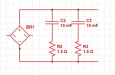
),am I understanding correctly? I used 10000uF and 1.5 as per previous suggestions.
Thanks a lot,
Stefano
Attachments
Stefano,
nope. Its easy to get confused, as this thread is covering multiple related topics simultaneously.
When Daniel talked about the 1.5R resistor (0.15R?), he was referring to sticking it in series with the lead connecting the DC supply (rectifiers & capacitors, like you've drawn) to the amplifier PCB, which has its own bank of capacitors (often called local decoupling)
this makes a C-R-C filter, with the R in series between the two cap banks (each cap bank goes to 0V).
as you've drawn it the 1R5 resistors increase the ESR of each 10mF cap, a lot. oops.
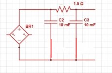
here is a badly re-drawn version. CRC = Shunt C + Series R + Shunt C
the series R-C that Daniel & I are discussing is something else again - we're talking about the (usually) 10R + 100nF R-C network from the amplifier output to 0V. confused? I am...
nope. Its easy to get confused, as this thread is covering multiple related topics simultaneously.
When Daniel talked about the 1.5R resistor (0.15R?), he was referring to sticking it in series with the lead connecting the DC supply (rectifiers & capacitors, like you've drawn) to the amplifier PCB, which has its own bank of capacitors (often called local decoupling)
this makes a C-R-C filter, with the R in series between the two cap banks (each cap bank goes to 0V).
as you've drawn it the 1R5 resistors increase the ESR of each 10mF cap, a lot. oops.
here is a badly re-drawn version. CRC = Shunt C + Series R + Shunt C
the series R-C that Daniel & I are discussing is something else again - we're talking about the (usually) 10R + 100nF R-C network from the amplifier output to 0V. confused? I am...
Attachments
Not badly re-drawn at all. Very nicely drawn.
Now Terry could add back in the esr of the caps to give a better model of the PSU.
Let's just guess at 40milli-ohms (0r04) for each 10mF capacitor.
Apply 50Vdc as the start up voltage and the first cap will draw an instantaneous current of ~1250Apk (50/0.04).
Ah, the model is not good enough yet. We need to add in the secondary resistance of the winding and add the resistance of the wiring loop and add the resistance of the rectifier and the back emf of the passing diodes. Note, I am deliberately misusing and...and...and etc., to get the message home.
Doing that may give an instantaneous worst case start up current of ~100Apk. That would be just 4V across the esr of that first cap. The other 46V gets lost in the other impedances. Estimated for this example at just less than half an ohm.
That esr is distributed across the VERY thin aluminium layer in the electrolytic. That esr heats up due to current, either or both AC & DC, passing between the plates of the capacitor.
Imagine inputting an instantaneous 400W (100^2*0.04) into that aluminium sheet !! Only for a microsecond !
The second cap in the CRC sees an instantaneous maximum current of just 24.7Apk for the same set of assumptions. This is ONLY 24.5W of dissipation in the esr of the second cap.
When you do a steady state Ripple Current assessment of the CRC and CLC PSUs you again find that the first cap has a severe ripple imposed on it. Be careful that you choose an appropriately specified cap for the first in a CRC/CLC PSU.
Often cheaper to select a bank of cheap lower value caps in parallel for this severe duty location, eg use 10off 2m2F instead of 1off 22mF. Save the expensive cap for the second stage. Better, maybe to use 2off 10mF.
I'll go and re-measure a 35+35Vac transformer. Volts and ohms only, I have not worked out yet how to do the complicated stuff.
See what happens with long posts. Folk get tired of reading them.
Last edited:
Ok,
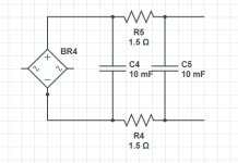
got it, thank you Terry and would you recommend one resistor only, or one resistor per rail, as I seem I recall?
(Drawings done on circuitlab.com).
For the "final" RC network, and for our 100W/8Ohm example amp I found a reference suggesting 1 Ohm/17W in series with 680nF (Solid State Power Amplifier Supply Part 3)
Don't know if it may be of interest.
Ciao,
Stefano
got it, thank you Terry
and would you recommend one resistor only, or one resistor per rail, as I seem I recall?(Drawings done on circuitlab.com).
For the "final" RC network, and for our 100W/8Ohm example amp I found a reference suggesting 1 Ohm/17W in series with 680nF (Solid State Power Amplifier Supply Part 3)
Don't know if it may be of interest.
Ciao,
Stefano
Attachments
Last edited:
I thought I had already done that! At least for Vrms, which is by far the strongest influence on Cres. I seem to keep repeating myself in this thread. Am I just wasting my time? I thought you had produced a formula too?gootee said:It seems that choosing the transformer VA and Vrms ratings is at least as important as choosing the total reservoir capacitance.
It would be nice to have a simple formula relating Vrms, VA, Pout, Rload, and Creservoir, that would also assume at least a bare minimum of 3V to 6V for the amplifier, between the bottom of the worst-case rail dip voltage and the top (peak output voltage) of the load.
Maybe someone can figure out (or already knows) how to add the VA and Vrms limitations to what we already have for Pout, Rload, and Cres.
In the early days of radio people didn't know how antennas actually worked, so they just played around with different lengths and shapes and established rules of thumb. Then one day someone had a good theory and said "Just put a quarter-wave length of wire straight up into the sky". At first they carried on bumbling around, believing that it couldn't be that simple. Eventually they realised that he was right.
Years later a new generation came along who for reasons we don't understand did not trust theory (or didn't understand algebra - we are not sure which it is). They started trying different antennas. An old-school engineer kept saying "Quarter-wave!", but they ignored him. Curiously, at the same time some of them began asking if anyone had a formula for the right length. How long before they 'rediscover' the right formula? (This story is not entirely historically accurate - it is told to make a point).
As I keep saying, to get the minimum cap value you need to do a ripple calculation (this involves Vrms, Vpk, Rload, Vdrop). You will find that the Cres depends critically on (1.414xVrms -Vpk - Vdrop=Vripple-max). Then double it. This will be close enough. There is little advantage in going bigger, and there may be disadvantages in going much bigger.
Stefano,
you've drawn a single power supply rail (lets call it V+). you certainly could split the resistor in two (each of half the value, so 0R75) and have a symmetric CRC filter as shown in your #1234. In many situations this type of symmetry is incredibly helpful - eg EMI filters are almost always symmetrical. I would suggest this is one time when its not a good idea.
in theory this doesnt change the circuit operation at all. in practice it does (it converts load current into common-mode voltage at the rectifier)
And where it all goes horribly wrong is when you add in the V- supply. Now what do you do with the 0V resistor? aaargh, brain explosion. I wont go through it in detail, because it turns out to be a terrible idea.
For a bipolar supply (V+ &V-) with CRC filtering, you'd have a single 1R5 in the +ve rail, and a single 1R5 in the V- rail.
Who is gonna develop the iphone, android app. A phone with measurement tools i.e. oscilloscope, distortion analyzer, VA and cap size calculator
I can do a Android app, just give me the inputs and what outputs you want based on formulas. The oscope and DA are out of my scope, and they can be done, but not by me...

- Status
- This old topic is closed. If you want to reopen this topic, contact a moderator using the "Report Post" button.
- Home
- Amplifiers
- Power Supplies
- Power Supply Resevoir Size