I have to catch a flight tomorrow morning and won't be back until late Thursday.
Just for the record, one standard way to estimate the required reservoir capacitance is something like the following:
1. Calculate the worst-case required input power, Pin, based on the output power (for both rails, total) and the efficiency. If efficiency is unknown, multiply the output power by at least 1.5.
If your output power spec is for a single sine wave, you should probably double it first, to account for the possibility of a square wave of the same peak amplitude.
2. Calculate the energy needed to provide the worst-case output power for one complete cycle of the AC line, W:
W = Pin / f, in Watt-Seconds (Joules), where f is the AC line frequency.
(The two rails' reservoir caps, together, should be able to provide the maximum load power with worst-case low AC line voltage and frequency, for one full cycle.)
3. Determine the peak voltage that could occur across the reservoir capacitor, Vpk. If nothing else, just use the maximum rectifier output voltage, i.e. secondary voltage x 1.414 minus two rectifier diode drops.
4. Estimate the minimum voltage that could occur across the reservoir capacitor, Vmin.
This can be done either by choosing a ripple voltage percentage (of nominal rail voltage) and calculating it from that (using worst-case lowest rail voltage), or by calculating the minimum allowable sum of the load voltage and the part of the amplifier that's between the load and the power rail. For the latter, it should be safe to use the maximum peak load voltage plus five or six volts, unless you can calculate the lowest possible allowable voltage across the amp more-accurately.
5. Then:
C (per rail) = 2W / (Vpk² + Vmin²)
For example, with a 44 VCT transformer and a 200-Watt (square wave) output spec:
W = 200 W x 1.5 / 60 Hz = 5 Joules (Watt-Seconds)
Vpk = 44 x 1.414 - 2 = 60 V
Vmin = 44 V (output peak voltage + 4 V)
C = (2 x 5) / (60² - 44²) = 3000 uF per rail.
16V of drop on the smoothing capacitor !!!..........................
Vpk = 44 x 1.414 - 2 = 60 V
Vmin = 44 V (output peak voltage + 4 V)
C = (2 x 5) / (60² - 44²) = 3000 uF per rail.
What about a 4V drop?
or a 2V drop?
or maybe a 1V drop?
Hi,16V of drop on the smoothing capacitor !!!.
What about a 4V drop?
or a 2V drop?
or maybe a 1V drop?
you just do not believe, yet it is a simple measure on trafo+capacitors.
i have measured for long time this, even in commercial high-end big amplifier. when in presence of sustain or continuos load, voltage decrease up to 14V in 800VA trafo. a this point, some think is not important for fidelity reproduction. others think it is very important, is searching for a possible solution, compatible with the cost and the heat produced. this is a new way I think, what you hear is completely different if the voltage does not drop in the moment of the peak. this has nothing to do with the nfb and PSRR
")
Absourd that i repeat and show some measure. why someone does not proceed with the measures?
Last edited:
You may have meant C (per rail) = 2W / (Vpk² - Vmin²), as used in your numerical example. You are equating energy lost from caps with energy sent to load, but then doubling it for luck. The doubling comes from dividing by f rather than 2f in step 2.gootee said:5. Then:
C (per rail) = 2W / (Vpk² + Vmin²)
In essence this is a ripple calculation, but done using energy instead of charge. The result should be the same. As I said, calculate C then double it.
I too have measured my PSUs and amplifiers.Hi,
you just do not believe, yet it is a simple measure on trafo+capacitors.
I would never accept a PSU design/build that dropped 16V, not even 8V, from no load condition to continuous full power condition.
I have seen 1V to 5V drops from reasonable supplies.
I have seen a commercial amplifier that has deliberately used a far too small transformer (actually pair of transformers) feeding into a far too small smoothing bank drop far too many volts when driving a specified 4r0 loading. But I would not accept that as a good PSU design. It was a good amplifier design in that the massive drop in PSU voltage helped prevent damage to the amplifier if the operator abused the amplifier. That is a quite different design brief. The result of that brief is that the amplifier is a pretty good 8ohms capable device.
Last edited:
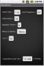
So can the calculations be done for the MAX amp power supply?
Given 110 volts 15 or 20 amps (or 220)
Mono amp or stereo amp with single transformer powering both
Max rail volts based on power output of amp
4 ohms or 8 ohms
Capacitance per rail =
Plug in the values and spit out the capacitance needed...
Maybe someone will make a smart phone app just for grins
Given 110 volts 15 or 20 amps (or 220)
Mono amp or stereo amp with single transformer powering both
Max rail volts based on power output of amp
4 ohms or 8 ohms
Capacitance per rail =
Plug in the values and spit out the capacitance needed...
Maybe someone will make a smart phone app just for grins
A spreadsheet would be wonderful!So can the calculations be done for the MAX amp power supply? Given 110 volts 15 or 20 amps (or 220) Mono amp or stereo amp with single transformer powering both Max rail volts based on power output of amp 4 ohms or 8 ohms Capacitance per rail = Plug in the values and spit out the capacitance needed...
I too have measured my PSUs and amplifiers.
I would never accept a PSU design/build that dropped 16V, not even 8V, from no load condition to continuous full power condition.
I have seen 1V to 5V drops from reasonable supplies.
I have seen a commercial amplifier that has deliberately used a far too small transformer (actually pair of transformers) feeding into a far too small smoothing bank drop far too many volts when driving a specified 4r0 loading. But I would not accept that as a good PSU design. It was a good amplifier design in that the massive drop in PSU voltage helped prevent damage to the amplifier if the operator abused the amplifier. That is a quite different design brief. The result of that brief is that the amplifier is a pretty good 8ohms capable device.
This is a fantasy that a psu with transformer, drop only 1-5V. sorry for this. if you have measure, please show.
and. it is very wrong to think 8R, (does not exist, a reactive load of 8R) in high fidelity equipments.
I add, continue only on theory and formulas, produces results far from reality. the first reason is that the 230AC is not perfectly sinusoidal, then the functions related to the cosine or sine must be adjusted by a factor. energy stored in the capacitor is wrong, if it is related to the period, then the capacity is incorrect.
--------------
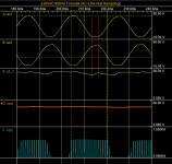
To study the solution, and keep near possible to the reality, I have created a model that is based on actual sampling of wave in the 230VAC socket of my laboratory. so I created the model of the transformer 800VA 50Hz high flux toroidal (with the manufacturer's specifications). At this point I connected a dynamic load. the result is visible in my last post with pic. please see drop voltage.
ac1 & ac2, are the signal on secondary of the transformer, see the waveform.
look also the voltage drop on main 8700uF capacitors.
I thought something like this would be kinda cOOLA spreadsheet would be wonderful!
Attachments
Obvious that 8700uF is not big.
condition is simple:
ac1 & ac2 probe on secondary of trafo.
c_Main = probe on main caps (8700uF)
r2P = probe on dissipation load (650w) it is a burst 1Khz with duration 16ms as see, connected at output of this psu (on main capacitor). this is all.
Orange track= same condition but probe at output of experimental regulator...ahah yes, this is vcc i need
Ew. The diode noise, the power line noise and loop noise all contributes higher charge to the capacitors when in unloaded conditions (a major problem for preamps); likewise, weak current noise makes artificially inflated voltage drop in power amplifiers. Yuk! If you didn't want that, then please filter it. For reference, see ham radio style power filtering. You should be able to reduce your voltage fluctuations by at least 2v. After filtering, the end result can meet AndrewT's 1v to 5v spec.This is a fantasy that a psu with transformer, drop only 1-5V. sorry for this. if you have measure, please show.
Also check out your under-load bridge rectifier forward voltage drop graph. Compare to the graph for KBPC3502 (looks almost like a straight up wall). A well snubbed KBPC3502 plus a transformer that has RC's applied across primaries and secondaries, will give you a more steady voltage due to reduced noise content. Noise filtering (parallel filters) and sturdy diodes--this works!
P.S.
Other possible problem for too much fluctuation is inrush resistors, crc, etc. . . that make caps take longer to charge, since series filters make a given transformer work like a much smaller transformer, and thus installing series filters IS re-visiting the question of whether or not your transformer is big enough. Earlier, I posted about a method for constraining the voltage drop of series filters by setting diode(s) parallel to the resistors for your choice of voltage drop limits (that resistors alone can't do because resistors work with current, not voltage). SO, you can have a CRC without epic voltage drop at high power.
Last edited:
AP2, measuring the secondary voltage does not give a scaled-down (by turns ratio) version of the AC line voltage. your rectifier-capacitor load is producing the flat-topped waveforms in conjunction with the transformer secondary leakage inductance. Although your AC line may well be slightly non-sinusoidal, in order to tell that you need to measure the AC line itself - or measure the unloaded secondary if you dont have isolated voltage probes.
Unless you have an amplifier as large as, say, a rolling stones concert, you wont affect the AC line voltage (hint: what is the rated power of the AC connection your house is connected to?).
And just for fun, try calculating the voltage THD
Unless you have an amplifier as large as, say, a rolling stones concert, you wont affect the AC line voltage (hint: what is the rated power of the AC connection your house is connected to?).
And just for fun, try calculating the voltage THD
Unfortunately, the mains is affected by all the ratty devices dragging power off it, which adds yet another layer of complexity upon this matter; it can be quite a mess. I've posted this link a couple of times, but for the sake of the conversation I'll add it here again: www.acoustica.org.uk.Unless you have an amplifier as large as, say, a rolling stones concert, you wont affect the AC line voltage (hint: what is the rated power of the AC connection your house is connected to?).
... (there is an eery silence as several sim's bite the dust) ...
With all this it's a wonder that amp's can produce anything like decent music ...
Frank
Frank, thats not bad - I've seen a much nastier picture than that: entirely missing cycles. it was at the end of a reasonably long transmission line (a few hundred km) and a local business had a spot welder making (IIRC) mattress assemblies. 20MW or so. every time it turned on the local supply collapsed completely. Some friends of mine were hired to fix the resultant power quality problems the rest of the small town experienced. their solution? buy everyone a UPS. which AIUI the company did.
you'll get the worst power in, say, an office block, where there may be hundreds or even thousands of rectifier-capacitor loads. this can and does set neutral conductors on fire (non-sinusoidal currents do not cancel in three-phase systems)
when it comes to measuring things like THD & PF of unity-PF SMPS, this is a real problem - most PFC work by forcing the line current to follow line voltage - so when testing you must use a clean voltage source, to get accurate, repeatable results. One simple test is to measure the PF & THD of a purely resistive load. if it aint 1 & 0, then all is not well with ones voltage supply.
we can draw some interesting conclusions from this:
1. even with perfectly sinusoidal mains, the rectifier-capacitor load at the end of the secondary (and primary) leakage inductance will still give a flat-topped secondary output voltage.
2. this is yet another good reason for a well laid out broadband DC bus (parallel plates again) if your cap bus is < 100mOhms up to 1MHz (easy to do) then it will attenuate the bajesus out of the AC line noise & harmonics
3. its also another good reason for the split DC bus approach, with the rectifier & first bank at the xfmr - all the mains harmonics & noise must still flow in the secondary wiring to & from the cap bank, so short (twisted) wiring will prevent it magnetically coupling elsewhere
4. Unless there is something horribly wrong with ones capacitor bank (say for example it is a typical audio one /snark), the attenuation of harmonics will be quite good - after all, they are designed to be nice and low-Z at the fundamental. This is where the transformer leakage is actually useful. Using Toms xfmr with L_leak_sec = 1.4mH and Cbus = 3mF, thats a 2nd order LPF with a corner frequency of 78Hz. rectified 3rd harmonic => 300Hz (yeah, I know, thats not the actual spectral characteristics of |sin(3wt)| but tis a reasonable approx & im lazy) so thats > 20dB attenuation.
4a. above some frequency the xfmr stops helping due to P-S capacitance - which is why screened xfmrs are used. But as with all EMI, the connection of the screens is paramount - any inductance in the screen connection to Earth is bad, as it not only now has a resonant peak, but above that frequency the screen shielding drops off with increasing F.
(I havent seen screened toroidals, but thats because I havent looked)
5. this is however a good reason to beef up the capacitor bank above the Gootee Minimum (although thats still pointless if the layout & wiring is lousy)
6. one sincerely hopes ones amplifier PSRR is good at LF, so any harmonic ripple that does get thru the cap bank wont modulate the output
7. using encapsulated CM/DM filter AC line sockets is a good idea, to clean up any nasty HF noise. these have excellent Earth connections, so you pretty much cant screw it up. any EMI filter that you have to supply the earth to is just asking for trouble...
I promise not to talk about PCC impedances.
Last edited:
Yes I do keep an eye on you thread. We started by aiming for large caps, then aimed for smaller caps but in all we have reached a conclusion we reached at the beginning . Keep up the good work guys.
But one thing is clear, its good to have a healthy transformer. Everything had already been sorted out here http://www.diyaudio.com/forums/power-supplies/216409-power-supply-resevoir-size-6.html#post3098034 , http://www.diyaudio.com/forums/power-supplies/216409-power-supply-resevoir-size-6.html#post3098067, http://www.diyaudio.com/forums/power-supplies/216409-power-supply-resevoir-size-8.html#post3098155 , http://www.diyaudio.com/forums/power-supplies/216409-power-supply-resevoir-size-10.html#post3099166 .
. Keep up the good work guys.But one thing is clear, its good to have a healthy transformer. Everything had already been sorted out here http://www.diyaudio.com/forums/power-supplies/216409-power-supply-resevoir-size-6.html#post3098034 , http://www.diyaudio.com/forums/power-supplies/216409-power-supply-resevoir-size-6.html#post3098067, http://www.diyaudio.com/forums/power-supplies/216409-power-supply-resevoir-size-8.html#post3098155 , http://www.diyaudio.com/forums/power-supplies/216409-power-supply-resevoir-size-10.html#post3099166 .
I have another potentially dumb trick with diodes.
The following example is using a 36vct (18,0,18) transformer and a CRC power supply.
For drainer resistor and a bonus light:
Per each rail. . . 10 of 2v orange led with each a 22k resistor.
That array looks like a 2v diode drop series to a 2.2k drainer resistor.
Notice that when the fridge or AC or vacuum cleaner is on, the diodes light up a bit brighter. Proportionately, this rather bright 2.2k bleeder resistor arrangement is wasting more noise than DC.
Since the example power board is a CRC, where do I put the diode+resistor drain for best effect (to waste more noise than DC), transformer side of the pi resistors (the "R" of the CRC) OR reservoir side of the pi resistors?
And, could I use power diode series to 2.2k to accomplish the same effect as the led's?
I ask because a black diode doesn't give an obvious indication.
Last edited:
- Status
- This old topic is closed. If you want to reopen this topic, contact a moderator using the "Report Post" button.
- Home
- Amplifiers
- Power Supplies
- Power Supply Resevoir Size