one more practical example
The ventilation slots under the capacitors are a nice touch.
Member
Joined 2009
Paid Member
I think that the power supply and amplifier need to be looked at together.
Agree
With large loudspeakers the bass response needs to be within a fraction of dB down to tens of Hz for no differences to be heard. That is difficult to achieve with a realistic sized output coupling capacitor so again a difference might be audible.
I don't think our ears are that sensitive at 10's of Hz to tiny variances although I've never tried it myself, besides in any normal listening environment the interaction of the speaker with the room boundaries make multiple dB changes to the flatness of the frequency response that are far in excess of any flatness issues from the amplifier (unless damping factor is so low that the speaker-amplifier combo produces it's own bumps in the FR due to impedance changes in the speaker with frequency).
My own thought on PSU cap sizes is that ripple is a bit of a red herring for the majority of gnf class AB amplifiers since they have very good PSRR. Class A is a different beast and the current draw requirements are so different from Class AB that I don't think one set of 'rules' works for both.
I believe that the frequency response of the power supply is more relevant. The output impedance as a function of frequency along with the transient response of the power supply to current demands from the output stage are more likely to affect the overall sound than low level ripple-induced hum. The use of chokes in the power supply can change these things drastically. I've never used a Shunt Regulator, but I suspect they level the playing field by maintaining a low output impedance and good transient response over a wide frequency range. They are power greedy though.
And the transient response is not about the caps, it's about the whole shebang, the transformer, rectifiers, caps, wiring and all of the associated parasitics. It seems to me, power supply design can be as complex and as important as the amplifier.
Last edited:
Example is CSA PCB in attachment. Nothing new but just one more practical example from the real build.")
If the power transistors are mounted between the big caps
this is an exemple of how it should not be done...
I have also heard of this rule of thumb, and we are on the opposite ends of the earth - is there a reasoning behind the rule (I was told this story in the 60s, but at the time it was only 1000uF/amp maybe easier calculations) Assuming all things equal, could the ripple only be responsible for "smearing" the sound. Does amps with better PSSR sound better than amps with lesser PSSR using the same power supply,.......
How much ripple maters depends on the rest of the amp. For example if the input stage and voltage amplifier stage are fed by a constant current source ripple would matter LOT less than if a simple resistor were used. A well designed amp should be very tolerant of power supply ripple.
But filter caps have another effect other then filtering out ripple, the caps are the power supply for the transistors. Transient response depends on having a low impedance power supply and having a few paralleled cap electro caps bypassed with film caps and proper wring can make for a lower output impedance. It depends on details of how this is done.
Those people who hear a difference when they add more capacitance may be hearing he lower output impedance and not the added capacitance. (Remember that ESR adds just like any other paralleled resistance.)
Other power supply effects matter too. For example mode switching noise and high order harmonic of that noise need to be "squashed" and some time high ESR caps work for that, Many times a resistor in series with a film cap is used to damp this radio frequency ringing on the supply. Again peole who change out filter caps may be effecting this and hearing more or less RF noise in the supply but thinking they are hearing the effect of more (or less) capacitance.
Andrej, your views have earned much respect on the forum, thank you for your comments.If the power transistors are mounted between the big caps
this is an example of how it should not be done...
Hugh, I respectfully disagree with your discarding the diode front end decoupling merely on grounds of simulation unless the simulations where carried out using a complex stimulus and a power source with finite impedance and you were able to distinguish between signal and signal modulated power rail.
The reason I am saying this is because I believe that the width/depth/sound-stage/imaging is a direct result of very low amplitude information contained in the recorder signal. By modulating the power rails due to large currents being drawn by low frequency or other high level signals, masks or smears the low level stuff in such a way that we lose the ambiance (provided of course that it was recorded in the first place).
This has nothing to do with the PSSR of the amp, it is not mains or ripple related, but high power signal related, it would not manifest itself in the FFT simply because the power supply rails are "singing in tune with the high intensity stuff"
Now I believe that Tom and Andrej (and yourself) may have unknowingly (or knowingly) solved the problem with a distributed power supply. I also believe that your earlier amps may have attracted a good following because they were capable of resolving the "ambiance" as it was recorded.
Guy's I am speculating here, but the reasoning seams plausible and I have definitely experienced a chalk and cheese sound difference between the battery and the power supply simply because the battery rails I believe were rock solid and modulation was not present on the small signal power lines. Therefor I would like to state an opinion in that I believe that the power supply has much more effect on the character of the sound than the amp itself.
Last edited:
Quote 'I don't think our ears are that sensitive at 10's of Hz to tiny variances although I've never tried it myself, besides in any normal listening environment the interaction of the speaker with the room boundaries make multiple dB changes to the flatness of the frequency response that are far in excess of any flatness issues from the amplifier (unless damping factor is so low that the speaker-amplifier combo produces it's own bumps in the FR due to impedance changes in the speaker with frequency).'
In an A/B comparison of electronics the low frequency response needs to be flat to not hear any differences between A and B. True it's academic because the differences are less than the Loudspeaker / room interaction.
In an A/B comparison of electronics the low frequency response needs to be flat to not hear any differences between A and B. True it's academic because the differences are less than the Loudspeaker / room interaction.
Andrew posted (about a month ago) that he was taking an extended holiday. Just how extended we don't know but best wishes to him.Where is AndrewT ? Its been nearly a month now since he was last on here.
Member
Joined 2009
Paid Member
I would like to state an opinion in that I believe that the power supply has much more effect on the character of the sound than the amp itself.
The tube guys have known this for 70 years already
assumed simplicity
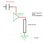
Attached is an example of a power supply
The 10NF capacitor ensures that some high frequency noise is cleaned up. The rectifier exibits good high frequency behaviour (it isnt switched by the remaining high frequency noise) because the large 10,000uF shouldnt have low impedance at those frequencies. Thus we have a well behaved supply giving us something close to D.C.
Something close to D.C. will not mind interconnecting cables and will safely charge the on board 33uF capacitors. These capacitors are sweet as they respond fast enough in the high frequency region to buffer the interconnecting cables. Thus What the amplifier sees is a stable DC supply.
Attached is an example of a power supply
An externally hosted image should be here but it was not working when we last tested it.
The 10NF capacitor ensures that some high frequency noise is cleaned up. The rectifier exibits good high frequency behaviour (it isnt switched by the remaining high frequency noise) because the large 10,000uF shouldnt have low impedance at those frequencies. Thus we have a well behaved supply giving us something close to D.C.
Something close to D.C. will not mind interconnecting cables and will safely charge the on board 33uF capacitors. These capacitors are sweet as they respond fast enough in the high frequency region to buffer the interconnecting cables. Thus What the amplifier sees is a stable DC supply.
The tube guys have known this for 70 years already
an audio amplifier is, fundamentally, a voltage controlled current source
of course the power supply is very crucial.
i for one am putting 2*15,000 μF on my 2*40 W chipamp
yeah the capacitors themselves will cost at least twice as much as the IC
something close to D.C.
don't want to sound like an ***hole, but: DC doesn't mean "constant voltage/current". Even after the rectifier it is DC. As long as it doesn't change direction, it still is DC.
Member
Joined 2009
Paid Member
yeah the capacitors themselves will cost at least twice as much as the IC
I think you made a wise choice because I read a lot of people found the quality of caps in the psu to be very important.

Andrew posted (about a month ago) that he was taking an extended holiday. Just how extended we don't know but best wishes to him.
Thanks for that Ian.
improved capacitor technology
There are very interesting caps now available
B41456B8109M EPCOS Inc | 495-4224-ND | DigiKey
There are very interesting caps now available
An externally hosted image should be here but it was not working when we last tested it.
B41456B8109M EPCOS Inc | 495-4224-ND | DigiKey
TThese capacitors are sweet as they respond fast enough in the high frequency region to buffer the interconnecting cables. Thus What the amplifier sees is a stable DC supply.
Okay Harrison, everyone describes that the power supply should produce good DC over a wide frequency range, but what affects your choice of value capacitor, it is surely not just an arbitrary number. Mind you I have seen comments on the forum like and I have xx 0000 uf caps..... results in solid bass, surely it is not just trail and error and you stop adding caps when you either run out of space or money.
Question is what made you choose these values why 33uF not 47uF or 10 uF. I would accept if you say from experience 33 uF sounds better than 47uF or if you have some formula (excuse the pun
) to calculate a specific value for a specific purpose, or a rule of thumb that has some historical significance.So far we have a few mathematical representations and several arbitrary choices of values, then we have some including myself that feel distributed power should be used and others that disagrees - we still do not have widely accepted set of rules that confidently indicates that the amplifier/power supply combination lives up to expectations?
Attached is an example of a power supply
An externally hosted image should be here but it was not working when we last tested it.
The 10NF capacitor ensures that some high frequency noise is cleaned up. The rectifier exibits good high frequency behaviour (it isnt switched by the remaining high frequency noise) because the large 10,000uF shouldnt have low impedance at those frequencies. Thus we have a well behaved supply giving us something close to D.C.
Something close to D.C. will not mind interconnecting cables and will safely charge the on board 33uF capacitors. These capacitors are sweet as they respond fast enough in the high frequency region to buffer the interconnecting cables. Thus What the amplifier sees is a stable DC supply.
It will depend on the amplifier being supplied, but...
There will not be constant current from the power supply. So the supply and ground conductors will have voltages induced across their parasitic inductances and resistances, by the time-varying currents. The only question is how much.
The 33uF is quite small. With a smaller decoupling capacitor like that, the rail voltage needs to drop more in order to cause any given increase in demanded current to be supplied by the cap. Also, if a demanded increase in current is too large for the cap to supply, the circuit will attempt to pull more of the current through the power rail conductor, which will likely have significantly more impedance than the cap, causing an even larger disturbance in the power rail voltage. Whether or not any of that will be significant depends on your application.
This setup might be OK (and more like you have desribed it) for a low-power amplifier that is for high frequencies only.
Otherwise, it should perform better with more attention given to implementing lower-inductance rail conductors (shorter, or multi-parallel) and more and/or larger-value caps in parallel at the load. It would also be improved by using multiple parallel caps in place of each 10k uF cap.
Okay Harrison, everyone describes that the power supply should produce good DC over a wide frequency range, but what affects your choice of value capacitor, it is surely not just an arbitrary number. Mind you I have seen comments on the forum like and I have xx 0000 uf caps..... results in solid bass, surely it is not just trail and error and you stop adding caps when you either run out of space or money.
Question is what made you choose these values why 33uF not 47uF or 10 uF. I would accept if you say from experience 33 uF sounds better than 47uF or if you have some formula (excuse the pun
So far we have a few mathematical representations and several arbitrary choices of values, then we have some including myself that feel distributed power should be used and others that disagrees - we still do not have widely accepted set of rules that confidently indicates that the amplifier/power supply combination lives up to expectations?
Determination of the minimum capacitance value needed at the point of load, and the maximum inductance in the cap and its connections to the load, are done using well-known methods. Well, they are well-known to the high-speed digital guys, anyway (see Henry W. Ott and Bruce Archambeault, for example). See the links I posted earlier, for the specific method(s).
- Status
- This old topic is closed. If you want to reopen this topic, contact a moderator using the "Report Post" button.
- Home
- Amplifiers
- Power Supplies
- Power Supply Resevoir Size