At very high frequencies, all inductors start to behave as capacitors and all capacitors start to behave as inductors.
If as an experiment you simulated your filter with the capacitors and inductors swapped over, what would be the effectiveness of the filter?
I added capacitance in my inductors and inductance in my capacitors in my simulations.
Since I will ditch the fuse, protection will be provided by a multislope current limiting circuitary. Since the fuse is not installed, I can freely use 12 x 680uF 100V low ESL capacitors totalling 8,560uF in power / ground planes near the output 2 x L-MOSFETs to reduce the inductance. I estimate that no matter how bad I do a design, the inductance at the L-MOSFET legs will be better than 15nH, or perhaps in the worst case 30nH, which would still give around -45dB PSRR at 20kHz.
As for the inductors in the main supply, I have learnt a bit. I often heard that most people tried using some RF inductors in power supply of power amps without success. I tried a few times. The result had been worse than without the inductors. Until recently I realised my mistakes. I previously thought that the fuse was rated 5-7A so the current shouldn't be more than 5-7A. I used inductors rated 5A. That was probably where the problem was. First, the 5A rating of the inductors usually refers to the maximum current of the inductors. If you really run it through with 5A you would find that the inductance may reduced to a small percentage. Secondly, once the inductor ferrite core is saturated, it produces distortions. When I checked with LTSpice with output drawing 5A current, the impulses passing through the inductors may be up to 30A! The inductors I used must be saturated, and that must be the reason I failed.
I then tried unwinding the 200uH-470uH inductors of low permeability toroidal ferrite core, even to 10uH the sound was still pretty awful. Until I reduced it to about 2.5uH, which consists of only 2-3 turns, I found that the sound was improved comparing to without the 2.5uH. I then checked with LTSpice and found that even 2.5uH still helps a great deal at higher frequencies.
Another good thing is that with only 2-3 turns the capacitance must be very small to be of any concern.
I have just bought myself dozens of larger, high permeability toroidal ferrite cores, and am planning to wind up to 10 turns on them. This would give more than 1mH inductance. I will see if they work.
You missed my point:
Now do a sim with only the parasitics, i.e. swap caps and inductors.
Your mistake was using a pair of differential inductors. They see the individual cable currents and saturate unless you use air cored.
You should look again at the RF filter, you will see a common mode inductor.
Both the cable currents pass their fields around the core and thus do not suffer from saturation, provided the earth leakage stays low to very low.
not just some added parasitics. The parasitics become dominant.At very high frequencies, all inductors start to behave as capacitors and all capacitors start to behave as inductors.
Now do a sim with only the parasitics, i.e. swap caps and inductors.
Your mistake was using a pair of differential inductors. They see the individual cable currents and saturate unless you use air cored.
You should look again at the RF filter, you will see a common mode inductor.
Both the cable currents pass their fields around the core and thus do not suffer from saturation, provided the earth leakage stays low to very low.
You missed my point:not just some added parasitics. The parasitics become dominant.
Now do a sim with only the parasitics, i.e. swap caps and inductors.
I don't understand why parasitics are not sufficient. With swaping caps and inductors, do you mean I need to take out all reservoir capacitors and replaced them with inductors?
Your mistake was using a pair of differential inductors. They see the individual cable currents and saturate unless you use air cored.
With differential inductors, would it saturate even if the core is now much bigger and the number of turns are reduced to only a few, i.e. much lowered inductance?
I have thought of air core inductors very hard. There are two problems. One is that the size gets big beyond 2.5uH. Second is it creates an electromagnetic field that may well transfer the noise to the adjacent circuits.
You should look again at the RF filter, you will see a common mode inductor. Both the cable currents pass their fields around the core and thus do not suffer from saturation, provided the earth leakage stays low to very low.
This sounds interesting. You mean that the magnetic fields created by the windings of a common mode inductor cancel each other hence prevent from saturation? Would the two windings of the common mode inductor be connected to the positive rail and negative rail? The wave forms are not symetrical though, so perhaps only 30% cancellation is achieved or something like that?
We are talking about mains interference filtering?
Or, have you moved to the DC side?
Similarly for an inductor, the parasitic capacitance completely takes over.
An LC filter when simmed will work.
Add a little bit of parasitic to the L and to the C and take the frequency even higher and the 2pole roll off comes to a limit.
Now change the filter to a CL where the parasitics dominate and at very high frequencies there is virtually no filtering (attenuation).
Or, have you moved to the DC side?
because at very high frequencies a capacitor does not behave as a capacitor. It behaves as an inductor, the parasitics dominate.I don't understand why parasitics are not sufficient.
Similarly for an inductor, the parasitic capacitance completely takes over.
An LC filter when simmed will work.
Add a little bit of parasitic to the L and to the C and take the frequency even higher and the 2pole roll off comes to a limit.
Now change the filter to a CL where the parasitics dominate and at very high frequencies there is virtually no filtering (attenuation).
Last edited:
The air cored in a rCLC filter will be located between the smoothing caps next to the transformer and rectifier..........I have thought of air core inductors very hard. There are two problems. One is that the size gets big beyond 2.5uH. Second is it creates an electromagnetic field that may well transfer the noise to the adjacent circuits...............
This gets the "location" away from the input stage of any Power amplifier if you design the layout appropriately.
A 50uH air core consists of ~60T of 1.2mm wire wound on a 19mm diam by 9mm long former. It takes up a similar space to a couple of 5W resistors and makes a very big difference to the "sharpness" of the ripple on the final smoothing capacitor.
So the air cored inductors are like those used in passive crossover network? With so many turns laying on top of each other the capacitance must be higher. It was for that reason that I wanted ferrite cored inductors instead.
Perhaps 10uH air cored inductors are more reasonable.
I looked up some datasheets of ferrite cored inductors and it appears that for the same size cores the lower the inductance the less chance the cores get saturated. From that pattern, I decided to try larger, high permeability cores aiming at low inductance.
Would the chance of saturation be less for a high permeability core than a low permeability core?
Last edited:
Having played around a fair bit with power supply inductors, I've found that ferrite cored aren't the best choice in this application. Better to go for iron powder core for a couple of reasons - first they're capable of higher flux levels than ferrite and second they have a much softer saturation characteristic. Ferrite's biggest selling point is its extremely low loss but in PSU applications this is relatively immaterial.
The highest inductance I've found in iron powder cores has been wih 'Sendust' - they generally have an AL (permeability) value of 125 (though 60 is also available). Given an AL value its easy to calculate the inductance - just multiply it by the square of the number of turns. The cheapest cores I've found are the type 26 which have a somewhat lower AL than Sendust. You'll find a lot of details of various cores here : Sendust Toroidal Cores for Chokes and Inductors : CWS ByteMark, largest supplier of toroids, ferrite cores, iron powder cores, MPP cores and RF cores
The highest inductance I've found in iron powder cores has been wih 'Sendust' - they generally have an AL (permeability) value of 125 (though 60 is also available). Given an AL value its easy to calculate the inductance - just multiply it by the square of the number of turns. The cheapest cores I've found are the type 26 which have a somewhat lower AL than Sendust. You'll find a lot of details of various cores here : Sendust Toroidal Cores for Chokes and Inductors : CWS ByteMark, largest supplier of toroids, ferrite cores, iron powder cores, MPP cores and RF cores
This is something I have learnt from this thread.
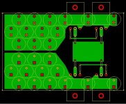
Attached is the drafted design of the output stage PCB.
I guess that the inductance should be low enough for 20kHz.
Each of the capacitors is a Rubycon ZLH 680uF 100V with Z=0.027 at 100kHz.
The ground plane is on the other side of the PCB and is not shown.
Attached is the drafted design of the output stage PCB.
I guess that the inductance should be low enough for 20kHz.
Each of the capacitors is a Rubycon ZLH 680uF 100V with Z=0.027 at 100kHz.
The ground plane is on the other side of the PCB and is not shown.
Attachments
Your mistake was using a pair of differential inductors. They see the individual cable currents and saturate unless you use air cored.
You should look again at the RF filter, you will see a common mode inductor.
Both the cable currents pass their fields around the core and thus do not suffer from saturation, provided the earth leakage stays low to very low.
Thank you so much, Andrew. After days of digesting I now really appreciate what you have said in the posts in this page.
It makes good sense to use CM chokes instead of Dif chokes.
Now a question. I know that AC current around a choke will create a magnetic field. I don't know if DC current around a choke will create a magnetic field or not. After the rectifier, the largest proportion of the current is DC current, not AC current.
I read that DC can saturate a ferrite core. So I guess in that case DC may create a magnetic field. If so, it is important to know that the DC in a CM choke also cancel each other's field.
CM chokes are fine if and only if you have CM noise/interference to get rid of. There seems to be modern fad for using them everywhere (so they only reduce total noise by 6dB) so be sure they are solving the right problem.
CM chokes avoid saturation by cancelling the magnetic field from the DC current. Of course, this will never be perfect as the wires are not in exactly the same place but it should be close enough. The AC field produced by the CM noise is not cancelled, otherwise the CM choke could not do its job. Thus you still have to be careful about unwanted coupling to other circuits.
CM chokes avoid saturation by cancelling the magnetic field from the DC current. Of course, this will never be perfect as the wires are not in exactly the same place but it should be close enough. The AC field produced by the CM noise is not cancelled, otherwise the CM choke could not do its job. Thus you still have to be careful about unwanted coupling to other circuits.
I think that in a CLRCLRC filter I am using for the power supply, anything else other than DC or the rectified mains waves (120Hz) is noise and should be filtered.
Now the question is, what percentage of that noise is differential? and what percentage is common mode?
Perhaps I can employ a common mode choke for the first L and then a differential choke for the second L (where peak current is reduced so there is less chance of saturation).
Now the question is, what percentage of that noise is differential? and what percentage is common mode?
Perhaps I can employ a common mode choke for the first L and then a differential choke for the second L (where peak current is reduced so there is less chance of saturation).
CM chokes are more optimally employed on the primary side of the trafo where the currents are lower. As to ratios, unless your mains is particularly noisy at least 99.9% of your PSU noise will be differential. However the frequency distributions are such that as the frequency rises the ratio of CM noise to DM will increase, I still can't see it rising above 1% though even at the top of the audio band.
Another factor to bear in mind is that the CM noise might well vary with what's connected upstream.
Another factor to bear in mind is that the CM noise might well vary with what's connected upstream.
I would expect most noise to be differential, due to normal transformer action. CM noise comes mainly from inter-winding capacitance, which can be small in a decent transformer. The primary is the best place to get rid of that.
I suspect that CM chokes have become popular because they are smaller and cheaper than a corresponding normal choke, but people don't understand what they do. Some people even try to use them for reducing ripple! It can be difficult to kill off a popular meme. Given that you are using resistance as your main smoothing method, there may be no need for chokes at all. Alternatively, why not just use a single ordinary choke (neither CM or differential) and good grounding techniques?
I suspect that CM chokes have become popular because they are smaller and cheaper than a corresponding normal choke, but people don't understand what they do. Some people even try to use them for reducing ripple! It can be difficult to kill off a popular meme. Given that you are using resistance as your main smoothing method, there may be no need for chokes at all. Alternatively, why not just use a single ordinary choke (neither CM or differential) and good grounding techniques?
I have bought dozens of high permissibility ferrite toroids and I can wind them as Diff or CM chokes. With these I get 100uH by doing only 3 turns. Capacitance is minimized.
From LTSpice simulations, a small amount of L, from as small as 2.2uH up to 10uH, does wonders above about 20kHz right up to MHz region. CRC with a typical small R of 0.1R to 0.22R without some L will reduce ripples / noise from around 1kHz to 20kHz, but won't do much above 100kHz due to the parasitic / wire inductance with capacitors. Unless SMT is used otherwise inductance may prevent the capacitors working in high frequencies. High Q capacitor can also cause ringing. With choke in series with R, no ringing occurs. With only a few turns I hope the chokes will have negligible amount of capacitance therefore can work until the MHz region. Also, with low inductance value I hope the cores won't get saturated.
It is for these reasons I found chokes to be useful.
I have some mild transformer/bridge resonances on my existing amp. Yesterday I made 3 turns on the high permeability ferrite toroids. They measured 60uH to 80uH. Put them on the amp. When the amp is idle the lines of the sinewaves on the scope look thinner, which is good. However, I don't have the set up to test them in high current. I could not subjectively determine if the sound is improved or not. The difference is obviously audible. It appears that upper midrange to lower treble is cleaner but I am not sure about the upper treble. This was compared to previously the low permeability core with 5 turns making up 2uH.
I found in the WES catelogue that they sell 18AWG 50uH loudspeaker air core inductors at a modest price. I am wondering if they suit PSU rails. I have not been thinking about loudspeaker inductors as I thought winding capacitance can be high. I guess I may need to buy 4 of them to try them out.
I found in the WES catelogue that they sell 18AWG 50uH loudspeaker air core inductors at a modest price. I am wondering if they suit PSU rails. I have not been thinking about loudspeaker inductors as I thought winding capacitance can be high. I guess I may need to buy 4 of them to try them out.
Last edited:
I love inductors.
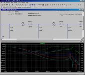
In the attached simulation, the green curve is for no inductors. The blue one is for 2uH. Only this small inductance makes filtering above 50kHz an order of a magnitude better. 10uH (red) and 50uH (cyan) are much better. But there is no reason to go beyond 10-50uH, really.
Without inductors, high frequencies are only attenuated slightly. Note that I have already made the inductance of the capacitors very small (4nH) as they are made up from a large number of small low ESL capacitors in a power / ground plane. If not, the high frequency filtering would be a lot worse.
If I failed with ferrite toroids due to saturation, I may have to use 2uH air core as the last resort.
PSUs really need some low capaictance inductors.
Attachments
Last edited:
Inductors may be the current fad, but I think you are tilting at windmills with this process of finding ways to solve probably non-existent problems. If there really is an RFI problem, the filter is best located before the power transformer, at lower current (as already posted) and before the stuff spreads around the inside your amp. There are already inexpensive, compact shielded filters for this application that may be much more effective.
If the problem you identified is diode commutation EMI, it will need much larger inductors than wispy little coils. You will need iron and lots of it, whether pressed powder or laminated. Such filters need to begin attenuating at anything above 100Hz rather than something up in the MHz region.
If you are serious about identifying and nailing RFI, you'll need to work with really good instruments - a bit beyond most DIY wallets unless you are able to get a good used 'scope and probe(s) with genuine >100MHz bandwidth.
I = C (dv/dt) is how they do it at Tektronix. dv = the amount of ripple you are willing to have, and dt = the amount of time between charge times (usually 1/120 seconds). High feedback amplifiers usually have inherent powersupply rejection that is such that you could be pretty far off and still have good sound. Hum is much more typically a result of poor grounding techniques in these circuits. In single ended topologies and/or very low negative feedback designs (more typical in the tube amp community) the power supply ripple goes right into the signal path and can be a problem.
- Status
- This old topic is closed. If you want to reopen this topic, contact a moderator using the "Report Post" button.
- Home
- Amplifiers
- Power Supplies
- Power Supply Resevoir Size