AP2,
Can we connect the load from + to - rail, excluding GND ?
I already explain this. (if you want use with amplifier) this smps want load on one side at time, even switched very fast. reason that is not good for two amp's,independant of total power.
for test yes, i have tested 10R to -vcc to +vcc at +/-62V. even for 10sec. i not see any problem.
Wired
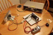
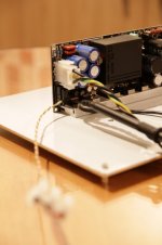
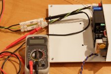
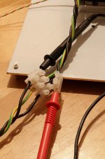
Those pics of how it was wired...
Not included the speaker [Mission 78cse 8Ohm] or mains leads.
Ran the setup friday night & saturday night for roughly 2hrs total with the resistors in place. Sunday; removed the resistors and it started fine without the O2/cd player connected. On for roughly 10 seconds before it was turned off. Connected the O2/cd player and turned on source - O2 - dps-600. unit started up then after roughly 6 seconds shut down with both led's blinking.
Attachments
Good table..eheh.
Some advice independant of all:
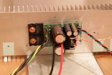
HeatSink is better connect to base panel of dps-600.
Connect heart of dps-600 (see my old pic for this) it is necessary,specially in this your connections.
Bias measurements:
in the measurement of bias, considered that the flow is transverse (not affected the load (speaker).
At 400mA,with your voltage setup, wire-amp dissipate 38-40w (only Mosfet) ..simple info.
Some advice independant of all:
HeatSink is better connect to base panel of dps-600.
Connect heart of dps-600 (see my old pic for this) it is necessary,specially in this your connections.
Bias measurements:
in the measurement of bias, considered that the flow is transverse (not affected the load (speaker).
At 400mA,with your voltage setup, wire-amp dissipate 38-40w (only Mosfet) ..simple info.
Last edited:
") Thanks, I'll implement those changes before doing enything else, plus add the standby switch. I will back off the bias and adjust anew...
Thanks, I'll implement those changes before doing enything else, plus add the standby switch. I will back off the bias and adjust anew... ah .. well! This is a special extra protection in the event fails the power regulator, just not to damage the amp, or other devices associated with the DPS-600.
I honestly do not understand how it can happen.
If you are able to replace the one mosfet smps, I can send, or you buy it, and I will refund.
looks like you have some damaging loop. in this case it is preferable that lowers the bias current, just to investigate the noise.
Am I looking to replace Q2, Q3, Q5... or something else?
have replaced the res-fuse on the first smps?
Not yet, the diode under the LM317 appears to be no good also, I'll replace it & the reg to be on the safe side.
I already explain this. (if you want use with amplifier) this smps want load on one side at time, even switched very fast. reason that is not good for two amp's,independant of total power.
for test yes, i have tested 10R to -vcc to +vcc at +/-62V. even for 10sec. i not see any problem.
What if 2 half bridge amplifier modules are connected to this smps and configured in bridge configuration, in that case the LOAD CURRENT will pass thru + to - rail without going into GND. Will it have same regulation or something different is expected?
This was the reason for asking again.
Right just Q2 [1 X IRFP250], had a quick look does it need to be 200V 33A or possible to use 200V 30A?
Thanks again, I WILL get it all working & trouble free
In your case, you need that after replacing, it go as original performances.
is not possible change mosfet model, just see voltage/amperes only. mosfet have other feature, as gate capacitance..etc.
Understood. Who's the manufacturer of this part, I ask as there is only a part code and no name. A search with digi-key shows two different Companies with the same product code IRFP250 but with different specs & both out of stock. As the others are STMicroelectronics parts I'd say this is also theirs?
If you do have one available, I'll be happy to send a paypal payment for it plus covering p&p and fees
If you do have one available, I'll be happy to send a paypal payment for it plus covering p&p and fees
Understood. Who's the manufacturer of this part, I ask as there is only a part code and no name. A search with digi-key shows two different Companies with the same product code IRFP250 but with different specs & both out of stock. As the others are STMicroelectronics parts I'd say this is also theirs?
If you do have one available, I'll be happy to send a paypal payment for it plus covering p&p and fees
I use IRFP250 IR. selected
sure that there are in stock, I can send you a couple if you also want the res-fuse, np, as I said before, I wanted to refund this expense.
remains the problem of shipping. (if you need something else, I'm available)
International Rectifier, now I've seen the thier logo I can just make it out on the the mosfet... IvR or something close. Lots in stock at digi-key so everything ok
Thanks for your help and patience. I'll update once I've got the parts & have the two dps-600's back up and running.
Lots in stock at digi-key so everything ok
Thanks for your help and patience. I'll update once I've got the parts & have the two dps-600's back up and running.
Hi, please send me PM with price you have payed.
So Close...
I really hate trying to find parts... I can't find the IR's IRFP250 which the data sheet says is a third generation HEXFET part... I have got an IRFP250M(PbF) which is IR's fith generation version. Shows A very slight variation within the datasheet...
Vishay do a IRFP250(PdF) which, as far as I can tell, is identical to International Rectifier's 3rd gen part used on the dps-600.
AP2, can I use the IRFP250M or better getting the Vishay part?
Hi Roberto,
I'm up to working on a heatsink temp threshold circuit to trigger DPS600 protection circuit.
If I have open collector LM339 comparator pulled up to 3V during normal operation, when temp input (TMP36) exceeds reference, comparator output connects to ISO gnd. Hysteresis needed to prevent amp from being re-enabled after protection triggers, until temp drops sufficiently.
Is that the intended operation for this connection?
Cheers,
Chris
Hi Chris,Hi Roberto,
I'm up to working on a heatsink temp threshold circuit to trigger DPS600 protection circuit.
If I have open collector LM339 comparator pulled up to 3V during normal operation, when temp input (TMP36) exceeds reference, comparator output connects to ISO gnd. Hysteresis needed to prevent amp from being re-enabled after protection triggers, until temp drops sufficiently.
Is that the intended operation for this connection?
Cheers,
Chris
I remember that you're using a logic that affects the remote control (2 pins), then you already have an isolator actuator. Close the remote control when the temp is higher. this is better, because it puts the DPS-600 as dead.
in both cases, you must provide a latch (remains closed until the temperature is high).
-----------------------------------
Break ISO pin, can be used to stop very quickly, eg. Fast photocoupler/circuit (OC) for overcurrent in amplifier.
This breaks only the operation of the PWM.
The remote control does two things. pwm break and disable / reset startup circuit.
regards
Roberto
Last edited:
I have chosed Intern. Rectifier becouse gate capacitance is very low (1150pF) vs. 1850pF Vishay.I really hate trying to find parts... I can't find the IR's IRFP250 which the data sheet says is a third generation HEXFET part... I have got an IRFP250M(PbF) which is IR's fith generation version. Shows A very slight variation within the datasheet...
Vishay do a IRFP250(PdF) which, as far as I can tell, is identical to International Rectifier's 3rd gen part used on the dps-600.
AP2, can I use the IRFP250M or better getting the Vishay part?
Obvius that dps-600 running but if we measure transient response, small capacitance model, have fast response (this mean small voltage drop) under current transient.
well, tomorrow i send a pair of mosfet+ res-fuse.
Hi Chris,
I remember that you're using a logic that affects the remote control (2 pins), then you already have an isolator actuator. Close the remote control when the temp is higher. this is better, because it puts the DPS-600 as dead.
in both cases, you must provide a latch (remains closed until the temperature is high).
-----------------------------------
Break ISO pin, can be used to stop very quickly, eg. Fast photocoupler/circuit (OC) for overcurrent in amplifier.
This breaks only the operation of the PWM.
The remote control does two things. pwm break and disable / reset startup circuit.
regards
Roberto
Thanks for the insight Roberto, I wasn't sure how different the shutdown method/sequence from remote vs isolated fast break would be. Your suggestion of just using the remote is really easy to implement with an AND gate between current logic and the isolated relay.
Getting close to having a schematic finished up in the next day or so, attached a block diagram of what I am hoping to end up with ...
Regards,
Chris
Attachments
- Status
- This old topic is closed. If you want to reopen this topic, contact a moderator using the "Report Post" button.
- Home
- Amplifiers
- Power Supplies
- DPS-600 fast regulated smps for Wire-Amp