I have a lot of info for better use this smps. i want your know well.
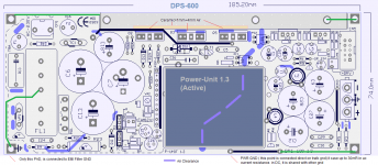
GND Planes on this smps, play in inverse philosophy. eg. heatsink is connected at output gnd (high voltage devices have double iso then).
As see on first pic, cross point of EMI filter, have separate gnd PAD.
this allow special use of dps-600. in your use,this PAD, must be connected to chassis gnd.
The other gnd points, are shared by a DC point of view. Power GND, allows the passage of large currents, especially in transient current, load-dependent.
Is not correct to pass this current (AC), on the amplifier circuits. (which may create distortions or strange sound effects on the envelope, not localizable with standard audio measurements)
----------------------
Remember, this SMPS (as DPS-500) has been developed around the amplifier, with continuous measures, on both, during development. I closed the project only when all parameters were perfect. eg, look at the shape of the signal at 100 Hz and behavior of the rail (opc measure). with another SMPS, the sine wave (at power) undergo many distortions, with alteration enormous output of current patterns.
------------------------------------------
I answer qusp (only yellow thing?) these are the snap-in (high-voltage electrolytic), are the only components that radiate emi (all SMPS, with varying intensities) (it is not clear that anyone who manufactures SMPS, knows this ).
your other questions I think are clear in this pic.
Attachments
Last edited:
Cool beans, thank you... With the two smps positioned together, is there a minimum gap needed between them. Or, can they be sited as close as possible without touching ... Was thinking of 5-10mm between them.
I think qusp's "yellow thing" refered to the base plate / heat dissipater [light yellow colouring], plus, do the measurements 70mm x 5mm refer to its required width & depth?
I've ordered an aluminium sheet [250mm x 250mm x 3mm] for the base, layout/sizing roughly as in the photo.
Paul.
I answer qusp (only yellow thing?) these are the snap-in (high-voltage electrolytic), are the only components that radiate emi (all SMPS, with varying intensities) (it is not clear that anyone who manufactures SMPS, knows this ). Your other questions I think are clear in this pic.
I think qusp's "yellow thing" refered to the base plate / heat dissipater [light yellow colouring], plus, do the measurements 70mm x 5mm refer to its required width & depth?
I've ordered an aluminium sheet [250mm x 250mm x 3mm] for the base, layout/sizing roughly as in the photo.
Paul.
Attachments
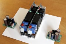
ah..yes, jellow light is a panel just pre-assemble smps-block..")
in your case, base panel 3mm is perfect.
the distance between the two SMPS, may well be 10mm. DPS-600 has no components that heat up (a little bit the power unit can have up to 35 ° delta). if it is possible, in the center to the two SMPS, there should be of the slots for the air flow. I understand that not everyone can create works on aluminum. a simple way, can be a saw to arco.start with a hole 5mm. another idea to help dissipate the heat, may be to raise eg 10mm, the aluminum base from the base of the case, this allows the circulation of air.
woW! very nice wire amp..is..small!
---------------------------------
I'm Wrong dimension in pic, panel is 80mm wide and 5mm thick. are measures of standard aluminum plate (metalwork in the city, it certainly can be ready ,Cut only the length)
i'm happy that you assemble in this way.
this is real audiophile dual-mono amp.
Last edited:
Thanks for the extra info Roberto, I think only slight variation on my photographed layout should get the results I am after. Will need to reconsider with thought of safety earth routing. That can happen another day as its 2am now
Ah but when the F1 race is on, there is one choice! Today Alonso was faultless.
@ hochopeper:
i love Ferrari but...dream Lamborghini "Gallardo jellow" ...
...stay tuned, AudioPower have a surprise about it, "Gallardo"..eheh!
Ah but when the F1 race is on, there is one choice! Today Alonso was faultless.
Hi, I'm back now,sorry for delay.
with the resistance can try the startup condition, yes. (one res per side)
After, connecting the amplifier. not try a single resistor between + and -. This SMPS also accepts loads on one side.
DPS-600 (without bottom panel) requires a cooling surface, min. 0.8-1 ° / W. for test eg. heatsink 160mmx40x40 thickness 10mm.
the final testing done in the laboratory, determines that the startup sequence, has a duration of 500ms with 2x373mA at output (2x150R load).
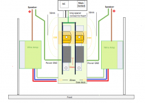
The best fitting both for the heat dissipated, which for EMI, is vertically on a base panel of aluminum 3mm thickness, used as the basis of the case.In this case, we recommend installing the two DPS-600, in central position of the case. This method may help the assembly, making no visible screws on the outside bottom of the lid of the case.
I wonder if these SMPS units is short circuit proof
And why the load cannot be connected to the + and - as you said?
Last edited:
Thought I could remember seeing a post by AP2 regarding pwr gnd... post #1193 in the main thread has a few usefull pics.
yes I remembered him answering, like I said, but I did a brief search for the answer before deciding it should be elaborated on here anyway. I was hoping there was an alternative, the hole at that point is quite small, considerably smaller than output ground, which is a bit odd. thats why I was hoping to use standoff and screw a ring terminal. it actually looks like I could do this with the front right corner standoff
many thanks for the detailed dimensions etc Roberto, ahh so by connecting the spacer across you mean through the AC filter ground? this appears in the picture to be connecting across something outside the boundary of the DPS600, thus my need for clarification.
yes the amp is very small AND very good, these amps will be compact, pretty and brutal =)
Roberto I just want to better understand your comment on lower right corner of first diagram. You've shown a note:
It saves 30mR compared to which alternative connection point? Relative to the 3pin DC output connector and amp pcb?
Power GND (this point is direct connected on traffo gnd) it save up to 30mR in ac resistance, in dc it is connected to other gnd
It saves 30mR compared to which alternative connection point? Relative to the 3pin DC output connector and amp pcb?
by front right I mean looking at it from the rear, looking at the front side its the left, seems pretty directly connected to the power earth point
Do you mean the one adjacent R3 & R5?
the corner next to R3, I read from Roberto that the point for power ground will be 30mR away at AC, but at DC same potential as the rest of the ground plane. since we are talking about AC return currents here from the speakers, it would seem better to use that PE point, but its got a hole that only fits 16awg solid vs. the 12awg solid that the output ground takes. so it seems to me for high power there is a trade off and the corner is the closest point to connect a large conductor.
a white line normally signifies a jumper, so it looks as if the option to connect these points was built into the PCB, but that for one reason or another they chose not to use it.
a white line normally signifies a jumper, so it looks as if the option to connect these points was built into the PCB, but that for one reason or another they chose not to use it.
Hi,
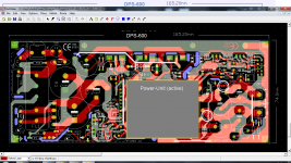
If we look at the PCB layers, at bottom of power gnd, gnd the layer that connects the output connector is 1cm thick, plus links to other reinforcement. you can put at bottom of the PCB, a PIN, 1.5 mm. and can also at bottom near power gnd pad, there are 3 pads, each with a 2mm hole, or solder jumpers (use solid wire 1.5 mm) and take the gnd, like you said, the pad at corner R3-R5. perhaps this is the most simple and clean. obvious that the gnd is already great, but when the current peak on load is high, things are not as they seem.
Kv3audio:
Yes, shortcut very well plus other protections.
One special is in case regulator fault, dps-600 break after 1 sec.
if connect resistor to + and - as load, smps running but in this smps not have sense this test. i explain before reason on this. (differential FB).
this SMPS, responds quickly to the demands of current, on one side at a time, as amplifier work. (opc measures), you can see the rail vcc behavior, with power signal 10Khz on amplifier.
Last edited:
thanks for the updated diagram Roberto, so its as I thought.
about AC ground, how about the large tinned rectangular pad under the PCB under the power unit? this seems ideal. I think I will use a chunky jumper from there (3-4 layers of 16awg silver foil, actually its more like flat wire than foil) and/or those 3 holes (although I dont really like soldering things from 'on top' of a hole) and put a ring terminal on the corner, then screw another ring terminal from there for the speaker return.
I may even use all 4 connected with ring terminals to the corner for reinforcement. I believe return conductors should be at least as big, preferably bigger than the signal conductor.
I really appreciate you posting the basic PCB layout mate, truly good form!
Just to be sure i will not make any stupid mistakes with startup, please see if this is correct:
1. Safety earth pad on DPS must be connected to output ground
2. For testing there must be load approx 150ohms at least on one output (-V to ground or +V to ground)
3. It is recommended to mount DPS vertically
4. Speaker GND must be connected to DPS ground, not amp ground
1. Safety earth pad on DPS must be connected to output ground
2. For testing there must be load approx 150ohms at least on one output (-V to ground or +V to ground)
3. It is recommended to mount DPS vertically
4. Speaker GND must be connected to DPS ground, not amp ground
Hi Kiwik,Just to be sure i will not make any stupid mistakes with startup, please see if this is correct:
1. Safety earth pad on DPS must be connected to output ground
2. For testing there must be load approx 150ohms at least on one output (-V to ground or +V to ground)
3. It is recommended to mount DPS vertically
4. Speaker GND must be connected to DPS ground, not amp ground
In general, as you said is correct. 180R resistor you can put two (one on each side to gnd) this just to turn on the DPS-600 and measure the voltage.
after that, if the wire is the first power amp, I recommend using two 22R resistors in series with the supply rails. This can help you adjust the bias and see if all is ok.
let me know how to go.
regards
- Status
- This old topic is closed. If you want to reopen this topic, contact a moderator using the "Report Post" button.
- Home
- Amplifiers
- Power Supplies
- DPS-600 fast regulated smps for Wire-Amp