Hi, i'm making an Amplifier based on two L12-2 Power Amps from ebay.
But as for the power supply I'm a bit comfused.
So, lets say that I have a toroid transformer 25-0-25 that I wire in series to output 50V, going to a bridge rectifier, then to 4 caps and a negative voltage generator (based on Voltages Regulators).
-First, is the output is still going to be -50v/GND/+50v with proper Voltage regulators?
-Second, what could be the proper voltage regulator for the power supply?
-And Third, is my schematic a good start or a bad idea?
I've roughly made a schematic, in the attachement, for what i think could be Ok...
Le Pick
Attachments
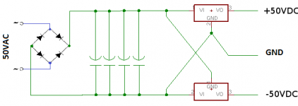
25V * sqrt(2) is 35.35V. Then you have the diode drop, so you will end up with ~34.5V, so from 25-0-25VAC you will have +/-34.5Vdc from across the filter caps before the regulator.
The circuit requires +/-50V, so with a diode drop you need ~51/sqrt(2) or ~36VAC....36-0-36. You need to reference the filter caps to the centertap or GND so you need two sets of filter caps to get +50VDC/GND/-50VDC.
The circuit requires +/-50V, so with a diode drop you need ~51/sqrt(2) or ~36VAC....36-0-36. You need to reference the filter caps to the centertap or GND so you need two sets of filter caps to get +50VDC/GND/-50VDC.
Last edited:
That PSU schematic is just wrong for many reasons :
1)you have to understand what a dual supply intended to be used with a power amplifier is , which brings to
2)that you don't need a regulated PSU for it ,then ..
3) the loudspeaker asks for current from the two poles , which are the output from the power transistors ( or mosfet ) and ground , so you just can't create a 'ground' ...
So , if the amplifier gives full power of 120 W on a 8Ω load with a dual 50 V supply ,
for the initial start-up you can power it up with your transformer ...it will give you
+ and - 35 V and less power at output . In the meantime find a 35+35 V...300W transformer !
Dual Rail PSU
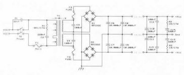
Let's let a picture paint a thousand words:
This is OVERKILL but explains the issue.
You require +50 - 0 - -50V PSU. Therefore in a high power situation you must have two secondaries, which indeed you have.
Each secondary MUST be capable of producing 50V in its own right, therefore you need a minimum of ~35V AC.
Ideally you would need about 37-0-37V AC to give you an unregulated 50-0-50 VDC but 35-0-35V AC would be close enough.
There are a number of ways of obtaining 50-0-50V DC from a 35-0-35 or 0-35 + 0-35V AC supply but they all require a split secondary winding.
Attachments
Ideally you would need about 37-0-37V AC to give you an unregulated 50-0-50 VDC but 35-0-35V AC would be close enough.
Assuming that I already have my transformer (Oups) that push 25-0-25 is there any way to do something with it or I did a bad mistake?
Why list the same question twice - This is against Forum Rules
http://www.diyaudio.com/forums/class-d/215834-negtive-voltage.html#post3086552
http://www.diyaudio.com/forums/class-d/215834-negtive-voltage.html#post3086552
Is the toroid sealed? If it is not, you can add more windings. Just use the same ga magnet wire as the secondary winding already there. Remove the outer insulation exposing the secondary winding. (the primary should be seperately insulated from the secondary inside) Wrap a few turns of wire around the core and measure the unloaded voltage. Then load the winding with a resistor and measure the voltage, ~1A or so. Divide by the # of turns and this will give you approximate V/turn. Add two seperate 10VAC windings so that each one covers the entire area of the core and place them in series with the ones already there so that you get 35-0-35VAC. This is one reason I like the toroid kits, easy to manipulate. That and the fact they are cheaper.
Last edited:
Is the toroid sealed? If it is not, you can add more windings. Just use the same ga magnet wire as the secondary winding already there. Remove the outer insulation exposing the secondary winding. (the primary should be seperately insulated from the secondary inside) Wrap a few turns of wire around the core and measure the unloaded voltage. Then load the winding with a resistor and measure the voltage, ~1A or so. Divide by the # of turns and this will give you approximate V/turn. Add two seperate 10VAC windings so that each one covers the entire area of the core and place them in series with the ones already there so that you get 35-0-35VAC. This is one reason I like the toroid kits, easy to manipulate. That and the fact they are cheaper.
i will say this is a unwise dangerous thing to suggest for someone who don't have a lot of experience! it is not just this and just that. is nothing just about rewind a transformer!
No more dangerous than handling filter caps with 100VDC. If you must use this transformer, it is a fairly simple task to add extra secondaries onto a large toroid, assuming it is not glued together, everything is on the outside, (under the outer polypropelyne tape insulation) no rewinding required. Just wrap two separate 10VAC windings in a bi-fillar manner on top of the existing secondary so they completely surround the toroid and connect each one in series to each end of the existing secondary(s), solder splice with heat shrink tubing. Then re-apply the outer polypropylene tape insulation. The primary and mains connections and the secondary that is already there would not be manipulated in any way. Of course, always check for electrical insulation between primary and seconday. I suppose a complete novice might not want to do this, but if you can properly assemble a stereo kit into an enclosure, this task ought to be fairly easy. If the transformer is too small, then you will certainly have to buy another one. For 240W of output power you would probably want something about 500VA. The expense of buying the wrong transformer can be a good lesson in learning to calculate the proper transformer size/voltage before you buy it. If you can get a refund, sell it, or use it for another project, that would be the easiest solution.
If you can get a refund, sell it, or use it for another project, that would be the easiest solution.then teare apart some 100V caps and re-build them and put 100V on them.
and pop a 100cap is less dangrous then having a transformer burn down the house do to bad insulation. or electric shock.
and if it works. it's a good chance the transformer windings will vibrate as hell.
not wourth for saving 10-20$ if you ask me.
and pop a 100cap is less dangrous then having a transformer burn down the house do to bad insulation. or electric shock.
and if it works. it's a good chance the transformer windings will vibrate as hell.
not wourth for saving 10-20$ if you ask me.
- Status
- This old topic is closed. If you want to reopen this topic, contact a moderator using the "Report Post" button.
- Home
- Amplifiers
- Power Supplies
- 50V Power Supply