is stable and strong
Attachments
-
2kwsmps.pdf123.7 KB · Views: 797
-
 IMG115-01.jpg531.3 KB · Views: 730
 -
 IMG116-01.jpg444 KB · Views: 661
 -
 IMG117-01.jpg497.1 KB · Views: 610
 -
 IMG132-01.jpg456.1 KB · Views: 555
 -
 IMG135-01.jpg521.6 KB · Views: 538
 -
 IMG139-01.jpg544 KB · Views: 300
 -
 IMG146-01.jpg524.8 KB · Views: 422
 -
 IMG152-01.jpg565.9 KB · Views: 397
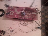
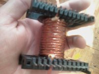
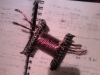
I give you an A for effort but i do not think you could really get 2KW out of this SMPS. First i belive the transformer should have primary winding’s closer to 30 turns each, not 15 turns (385vdc, 50khz, 1800Gauss at 80Deg C, Ae 3.68). Second, your homemade litz wire with 14 x .45mm wires would have a RAC around 5. My calculations show you are running about 3000 Gauss, the limit of N87 ferrite.
You say it is running stable and strong at 92% efficency? I find that hard to belive. Even if the transformer was not running saturated, the high RAC would make efficency very low.
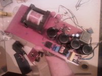
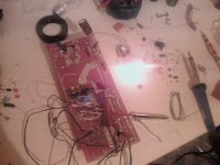
I would like to hear how you tested this SMPS and to hear from others about their thoughts on this. Because the build is well documented with pictures and has an informative schematic it is easy to run calculations on this design. I think this could be a good learning experience for all of us.
You say it is running stable and strong at 92% efficency? I find that hard to belive. Even if the transformer was not running saturated, the high RAC would make efficency very low.
I would like to hear how you tested this SMPS and to hear from others about their thoughts on this. Because the build is well documented with pictures and has an informative schematic it is easy to run calculations on this design. I think this could be a good learning experience for all of us.
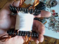
I took another look at this SMPS today and looked at the secondary. It is 16 strands of .65mm and it looks like the transformer was wound as Pri, Pri Sec. This would give an RAC on the secondary of at least 18.
I would sure like to know how much power this SMPS could actually deliver for a length of time and what temperature the core reached.
I would sure like to know how much power this SMPS could actually deliver for a length of time and what temperature the core reached.
I took another look at this SMPS today and looked at the secondary. It is 16 strands of .65mm and it looks like the transformer was wound as Pri, Pri Sec. This would give an RAC on the secondary of at least 18.
I would sure like to know how much power this SMPS could actually deliver for a length of time and what temperature the core reached.
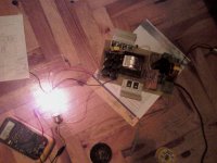
yes 300w load MOSFETs too hot, but warm transformer
I incorrectly calculate the primer
and also makes noise amplifier
why on earth you used push-pull for offline? to prove a point?
what main transistors did you use?
hi luka main transistors is ihw20n120r3
400KG, i think you did a good job choosing your switching transistor. For 240vac input you need at least an 800vdc rated transistor and yours is 1200vdc. You also have plenty of current for switching with a 20 amp rating.
The concern with push pull besides the high voltage rating needed for the transistor is that push pull topologies tend to have a flux walking problem. If the core becomes unbalanced from slightly different primary winding’s or uneven heating of the transistors the transformer flux will start to walk either to the positive side or negative side and the transformer will saturate. The only fix for this is a very high speed current sense circuit to give you a cycle by cycle current limit. This problem can be totally avoided by using a half bridge driver that has a capacitor in series with the primary winding to continually adjust transformer imbalance.
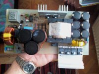
You might want to look at your output section also. You have many 470uF capacitors paralleled up but no high frequency high current capacitors. I belive those 470uF capacitors will have a short life in this application.
The concern with push pull besides the high voltage rating needed for the transistor is that push pull topologies tend to have a flux walking problem. If the core becomes unbalanced from slightly different primary winding’s or uneven heating of the transistors the transformer flux will start to walk either to the positive side or negative side and the transformer will saturate. The only fix for this is a very high speed current sense circuit to give you a cycle by cycle current limit. This problem can be totally avoided by using a half bridge driver that has a capacitor in series with the primary winding to continually adjust transformer imbalance.
You might want to look at your output section also. You have many 470uF capacitors paralleled up but no high frequency high current capacitors. I belive those 470uF capacitors will have a short life in this application.
400KG, when you rewind your transformer you must use less wires. Your RAC is to high.
Proximity effect (electromagnetism) - Wikipedia, the free encyclopedia
You will be much better off using 4 strands of .45mm for the primary and 3 strands of .65mm for the secondary. You will not have enough wire diameter for continuous 2kw output but it will be OK for a 2kw music system.
Proximity effect (electromagnetism) - Wikipedia, the free encyclopedia
You will be much better off using 4 strands of .45mm for the primary and 3 strands of .65mm for the secondary. You will not have enough wire diameter for continuous 2kw output but it will be OK for a 2kw music system.
powerbob:
This has been widely discussed on this forum before
If you have a cap in series with pri then you MUST use voltage mode only.
And if you use voltage mode then what happens when it goes on overload.......well, it goes into cycle by cycle current limit, because all voltage mode half bridges need a pri current limit.......and when you go into cycle by cycle current limit then your half bridge rail splitter cap voltage drifts, which means you need to size the splitter caps for the full rail voltage which meakes them very very expensive.
Without a series cap you need to be in current mode with a half bridge.......but if in current mode then you need to have "average current mode" as per the LM5039....otherwise you rail splitter cap voltage will drift again
LM5039
http://www.ti.com/lit/ds/snvs621c/snvs621c.pdf
So i would choose full bridge over half bridge, unless you use the LM5039.
This problem can be totally avoided by using a half bridge driver that has a capacitor in series with the primary winding to continually adjust transformer imbalance.
This has been widely discussed on this forum before
If you have a cap in series with pri then you MUST use voltage mode only.
And if you use voltage mode then what happens when it goes on overload.......well, it goes into cycle by cycle current limit, because all voltage mode half bridges need a pri current limit.......and when you go into cycle by cycle current limit then your half bridge rail splitter cap voltage drifts, which means you need to size the splitter caps for the full rail voltage which meakes them very very expensive.
Without a series cap you need to be in current mode with a half bridge.......but if in current mode then you need to have "average current mode" as per the LM5039....otherwise you rail splitter cap voltage will drift again
LM5039
http://www.ti.com/lit/ds/snvs621c/snvs621c.pdf
So i would choose full bridge over half bridge, unless you use the LM5039.
- Status
- This old topic is closed. If you want to reopen this topic, contact a moderator using the "Report Post" button.
- Home
- Amplifiers
- Power Supplies
- 2kw pull-push offline smps