I have two nice lab supplies which do 18 V at 20 A.
The manufacturer also makes 36 V at 10 A, nearly identical. That is what I want, so I can use them for amp testing.
They are based on SMPS followed by a linear regulator. The differences are around the lower current rating of the 36 V supply: smaller 10 A filter choke, lower value and voltage filter caps, fewer pass transistors and smaller heatsinks in the linear section, different transformer. Other than that, the differences are small, just some resistor values to account for different V/I ranges. (I have access to full schematics).
The transformer is the sticky part. The secondary voltage is about 35 to 40 Vp-p which is not enough. But it is wired as half-bridge rectified. If I convert to full-bridge, I get twice the voltage (and ~half the current capability) which is exactly what I want. Refer to attachment.
The secondary rectifier is a FRED, not exactly modern high-tech stuff. Should I replace it with Schottkys or get more FREDs to make the full-bridge? Fs ~= 100 kHz, Vp-p would be ~70 to 80 V.
SMPS is not my area of expertise, so I ask you: is it OK to do what I planned? Or is there some important consideration I am missing that will make it impossible to use the present transformer in this way?
Attachments
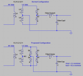
Both circuits are full wave rectification. Your original circuit just uses full wave center tap meaning only half of the transformer is used at one time, thus you get half of the voltage. The 4 diode bridge connected across the full transformer winding gets the full transformer voltage so it can give twice the output voltage over the center tapped version.
You can use the original 20 amp inductor for the 10 amp circuit and it will actually work better than it did before. It will run cooler and regulate the current down to a lower value of about half of what it used to.
Stick with the mfgr original diodes if the physical sizes matches up, such as lead spacing and bolting up to the heat sink. Fred diodes have a good reputation, and the mfg has a tried and true design.
The linear section sounds like it could be a problem. there is a lot of unknown there of exactly how it functions. I would think the SMPS does the coarse regulating and the linear section just cleans up the output. This would mean that they are somehow connected and work in sync.
I would like to see both schematics, parts list, and a few pictures of its construction before i comment further.
Changing the rectifier to full bridge should work fine. Total rectifier losses at the new maximum output current will be the same as before the change. The drawback of doing it this way is that you could have halved them if the transformer was rewound instead.
I'd be very interested in the schematics and/or the make and model, if you could post them.")
Could you elaborate on what you mean the voltages are? Do you really mean peak-to-peak as opposed to peak value? 35 V peak-to-peak (alternating +-17.5 V) measured from one transformer end to ground would not be enough for 18 V output.
If you were to do that your ripple current would double because you have doubled the voltage across the inductor. So if you start with a delta-I of 4A, 20% of full load current, you'll end up with a delta-I of 8A which is 80% of the new full load current. The converter will then run in discontinuous mode up to 4A of output current.
Core losses will also increase by about 4 times, because they are approximately proportional to the flux density swing squared. Whether the core loss increase is going to be a problem or not depends on how significant it was to start with. For a ferrite core inductor it would be low and maybe okay, but with iron powder or similar materials you're likely to be in trouble.
Doubling the number of turns on the inductor and halving the wire area (giving 4 times the inductance and resistance) will give you the same relative ripple current amplitude, core losses and copper losses as before.
If you scale the output capacitors of the SMPS part in the corresponding way, a fourth of the original capacitance and four times higher ESR, the only change needed to the control loop to give the same loop gain shape as you had from the start is to halve its gain.
I'd be very interested in the schematics and/or the make and model, if you could post them.
Could you elaborate on what you mean the voltages are? Do you really mean peak-to-peak as opposed to peak value? 35 V peak-to-peak (alternating +-17.5 V) measured from one transformer end to ground would not be enough for 18 V output.
You can use the original 20 amp inductor for the 10 amp circuit and it will actually work better than it did before. It will run cooler and regulate the current down to a lower value of about half of what it used to.
If you were to do that your ripple current would double because you have doubled the voltage across the inductor. So if you start with a delta-I of 4A, 20% of full load current, you'll end up with a delta-I of 8A which is 80% of the new full load current. The converter will then run in discontinuous mode up to 4A of output current.
Core losses will also increase by about 4 times, because they are approximately proportional to the flux density swing squared. Whether the core loss increase is going to be a problem or not depends on how significant it was to start with. For a ferrite core inductor it would be low and maybe okay, but with iron powder or similar materials you're likely to be in trouble.
Doubling the number of turns on the inductor and halving the wire area (giving 4 times the inductance and resistance) will give you the same relative ripple current amplitude, core losses and copper losses as before.
If you scale the output capacitors of the SMPS part in the corresponding way, a fourth of the original capacitance and four times higher ESR, the only change needed to the control loop to give the same loop gain shape as you had from the start is to halve its gain.
Last edited:
They are Thurlby TSX1820. The 36 V 10 A model is TSX3610. I won't distribute the service manual, but you may have luck getting it just by nicely asking Thurlby tech support for it. it is Book Part Number 48511-0240, or "TSX Series High Current Power Supplies Service Manual".Changing the rectifier to full bridge should work fine. Total rectifier losses at the new maximum output current will be the same as before the change. The drawback of doing it this way is that you could have halved them if the transformer was rewound instead.
I'd be very interested in the schematics and/or the make and model, if you could post them.
I was referring to the PWM voltage waveform at the output of the power transformer, it is ~80 V peak to peak (measured across the entire secondary), not including ringing or other artifacts. Measured from center tap it is of course half that (~40 Vpp).Could you elaborate on what you mean the voltages are? Do you really mean peak-to-peak as opposed to peak value? 35 V peak-to-peak (alternating +-17.5 V) measured from one transformer end to ground would not be enough for 18 V output.
I hadn't thought about ripple current increasing, but it makes complete sense of course. I suppose that this will result in double the resistive heating of the inductor windings due to ripple current, but maybe this will be offset by less resistive heating due to load current (10 A instead of 20 A)? What about fear of saturation?If you were to do that your ripple current would double because you have doubled the voltage across the inductor. So if you start with a delta-I of 4A, 20% of full load current, you'll end up with a delta-I of 8A which is 80% of the new full load current. The converter will then run in discontinuous mode up to 4A of output current.
I have to admit I don't understand your statement about discontinuous mode (remember SMPS is not my forte).
The inductor resembles an EI transformer, but it is an inductor. So it is a laminated core, and it uses ribbon windings, not wire. It is large, very approximately 2"x2"x2".Core losses will also increase by about 4 times, because they are approximately proportional to the flux density swing squared. Whether the core loss increase is going to be a problem or not depends on how significant it was to start with. For a ferrite core inductor it would be low and maybe okay, but with iron powder or similar materials you're likely to be in trouble.
Due to the EI & ribbon construction of the thing, I don't think I will be doing that. I hope it will work as-is. I'll examine it closely later; maybe if I am really lucky there will be two sets of windings that are paralleled, and I can re-wire them in series (that would work right?). Maybe, just maybe, they built them that way so that they didn't need to have two different custom inductors wound for the two different models.Doubling the number of turns on the inductor and halving the wire area (giving 4 times the inductance and resistance) will give you the same relative ripple current amplitude, core losses and copper losses as before.
The prospect of re-engineering the control loop is not very enticing, so making changes that are compatible with it sounds like a good idea.If you scale the output capacitors of the SMPS part in the corresponding way, a fourth of the original capacitance and four times higher ESR, the only change needed to the control loop to give the same loop gain shape as you had from the start is to halve its gain.
Thanks very much megajocke for the very detailed reply. You gave exactly the kind of response I hoped for, with good information and insights.
I was thinking that if it had been a toroid, like usually used in PC power supplies, it would have been easy to rewind... Not so lucky! Just make sure you check that the inductor isn't overheating. Worst case heating is at 50% duty cycle, maximum load current and high line. And by 50%, just to be specific because there are a few different conventions used in bridge topology, I mean a switching sequence of 25% positive, 25% off, 25% negative, 25% off - which gives a 50% duty cycle square wave feeding the LC filter.
For the output capacitor, in this case, it should be the same as before the change but of course with a sufficient voltage rating. Control loop gain will double in this case too, but might or might not be within the original design margins.
For the output capacitor, in this case, it should be the same as before the change but of course with a sufficient voltage rating. Control loop gain will double in this case too, but might or might not be within the original design margins.
I took a look at the thing last night, and the inductor appears to be ferrite core, but it is not a toroid, it is EI style. (The transformer appears also to be EI ferrite). The windings appear to be litz wire, not ribbon like I thought (there is a copper foil around the winding and that had decieved me), and even better, I think there are in fact two windings paralleled. So I can probably re-wire the two windings in series.
So if I keep the inductor the same, I should keep the filter capactiors the same too. If I modify the inductor, I should use 1/4 the capacitance, right? In either case, since the voltage at the rectifier is doubled, loop gain has doubled and I should probably account for that in the control section.
So if I keep the inductor the same, I should keep the filter capactiors the same too. If I modify the inductor, I should use 1/4 the capacitance, right? In either case, since the voltage at the rectifier is doubled, loop gain has doubled and I should probably account for that in the control section.
Ok!
Yes, that seems correct. And that's actually the capacitance given by the TSX3510 parts list.
Doubling the value of R128 should put the loop gain back where it was, but it will also limit optocoupler current to a lower value. Depending on its initial value, this could be a problem because the maximum duty cycle might be reduced, as I wrote in the email.
Intro / question
Hi all,
After having noticed this forum and the ongoing discussion I thought it would be worthwhile to join. I am not professionally involved in the audio world but audio is a natural part of my hamradio hobby.
Initially I have a (literally) burning question about some components from a TSX3510 PSU that once were but no longer are....This happened during a calibration procedure of a big NiCad charger for aircraft batteries (I work for a regional airline). Two MOSFETs, some capacitors and some resistors were fried...clear proof that the NiCad charger was the fighting winner....if I had ever been in doubt!
I already replaced the MOSFETs Q1 and Q2 and the capacitors but the resistors R22 and R10 (plus the duplicate set of resistors next to them) are open and completely lost their coating and thereby their value indications. I noticed that you guys have been able to come over part lists for this PSU so I wondered if you could help me with the values of R22 and R10. If I'm right this information could bring the PSU back to life again.
/Ron
Hi all,
After having noticed this forum and the ongoing discussion I thought it would be worthwhile to join. I am not professionally involved in the audio world but audio is a natural part of my hamradio hobby.
Initially I have a (literally) burning question about some components from a TSX3510 PSU that once were but no longer are....This happened during a calibration procedure of a big NiCad charger for aircraft batteries (I work for a regional airline). Two MOSFETs, some capacitors and some resistors were fried...clear proof that the NiCad charger was the fighting winner
....if I had ever been in doubt!I already replaced the MOSFETs Q1 and Q2 and the capacitors but the resistors R22 and R10 (plus the duplicate set of resistors next to them) are open and completely lost their coating and thereby their value indications. I noticed that you guys have been able to come over part lists for this PSU so I wondered if you could help me with the values of R22 and R10. If I'm right this information could bring the PSU back to life again.
/Ron
Okay thanks for your info!
I replaced the four resistors and things appeared ok at first, showing the voltage and current on the display. But as soon as the output ON button is depressed the unit switches to TRIP on the voltage and current displays. A red led on the circuit board also comes on. So I am clearly not done yet!
/Ron
I replaced the four resistors and things appeared ok at first, showing the voltage and current on the display. But as soon as the output ON button is depressed the unit switches to TRIP on the voltage and current displays. A red led on the circuit board also comes on. So I am clearly not done yet
!/Ron
- Status
- This old topic is closed. If you want to reopen this topic, contact a moderator using the "Report Post" button.
- Home
- Amplifiers
- Power Supplies
- Convert SMPS from half to full bridge