hi guys
i make this threads for car audio smps
please help to your friends to make smps for car
i have TL494 IC and ETD39 and IRFZ44n mosfet.
is this good?
can you help me please?
i make this threads for car audio smps
please help to your friends to make smps for car
i have TL494 IC and ETD39 and IRFZ44n mosfet.
is this good?
An externally hosted image should be here but it was not working when we last tested it.
An externally hosted image should be here but it was not working when we last tested it.
can you help me please?
Last edited:
Did you miss this thread?
http://www.diyaudio.com/forums/class-d/214621-sg3526g-pwm-regulated.html#post3062317
Cheers !!
jer
http://www.diyaudio.com/forums/class-d/214621-sg3526g-pwm-regulated.html#post3062317
Cheers !!
jer
thank you dear friendDid you miss this thread?
http://www.diyaudio.com/forums/class-d/214621-sg3526g-pwm-regulated.html#post3062317
Cheers !!
jer
i have about 800 number of TL494 and 1000 number of IRFZ44N and 300 number of ETD39.
please help me to make smps with input 13.8 volt and output + - 25V AC
thank you
sorry for my bad english
Basically the recipe is in that thread.
You will have to reduce the amount of turns on the secondary to about 8 to 10 turns.
And change the voltage divider ratio of R112+R104 and R105 from 20:1 to 10:1.
Follow that the pins are connected for the same functions.
I haven't messed with these types of circuits yet but it is pretty straight forward from what I can see.
As I mentioned before you can simply add a small trimmer pot in the voltage divider in order to have a fine adjustment of the output voltage.
That is the best as far as I can tell you since I have not made one myself yet.
The only thing stopping me from trying it is that I don't have any ETD cores.
But I do have an idea to use a larger toroidal power transformer in order to get a higher power capability out of it due to the higher than 60Hz switching frequency.
Here is the data sheet for the ETD34,
http://www.epcos.com/inf/80/db/fer_07/etd_34_17_11.pdf
And here is the data sheet for the ETD39,
http://www.ferroxcube.com/prod/assets/etd39.pdf
According to the data sheets the ETD39 is only slightly larger in size and has about a 10% higher Al value as well, this is good.
You shouldn't have any issues with core saturation with the same amount of primary turns because of this.
As long as the switching frequency is the same as that for the SG3526 layout.
Good Luck !!
jer
sorryYour link goes to a site that requires me to install a downloader or something and it does not take me to the actual PDF for viewing.
Please post the actual url to the PDF so that it can be seen.
jer
is this ok?
Attachments

please give me your email adress for send PDF file in a email.Your link goes to a site that requires me to install a downloader or something and it does not take me to the actual PDF for viewing.
Please post the actual url to the PDF so that it can be seen.
jer
thanks
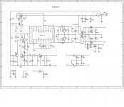
I can now see the schematics.
Are you familiar with the operation of the TL494 ?
Here are some data sheets and application notes that will help you,
http://www.ti.com/lit/ds/symlink/tl494.pdf
http://www.ti.com/lit/an/slva001e/slva001e.pdf
http://www.onsemi.com/pub_link/Collateral/AN983-D.PDF
http://www.onsemi.com/pub_link/Collateral/TL494-D.PDF
http://bbs.dianyuan.com/bbs/u/30/1120101537.pdf
I know it seems complicated as it took me a while to understand switching supplies, But they really are easy once you understand what is going on.
The output pins of the chip are more suited for BJT's so a driver circuit for FET's is the best way to go to insure a complete turn off state of the device at high frequency's.
I found this out when I was designing my HV variable supply for ESL's.
I found that the npn/pnp bjt configuration worked the best as I was designing for a 100Khz to 200Khz range.
But, There are driver chips that are designed to do this and requires little too no extra parts.
Such as the IRF 2111 Series of driver chips (IRF211x).
http://www.irf.com/product-info/datasheets/data/ir2110.pdf
http://www.irf.com/product-info/datasheets/data/ir2111.pdf
http://www.irf.com/product-info/datasheets/data/ir2112.pdf
http://www.irf.com/technical-info/appnotes/an-978.pdf
http://www.irf.com/technical-info/appnotes/an-1108.pdf
I didn't have any so I just used BJT's instead.
I started off with a single FET driven off of a 555 timer but I had to add the BJT buffer stage in order for it to switch properly.
Then I added a driver transformer for the push pull setup.
This can be done as well but the TL494 already has a complementary output so it is not needed, Just the drivers are.
My power supply can be found here just for reference of the driver configuration,
http://www.diyaudio.com/forums/plan...tor-insulation-mylar-coating.html#post2531218
http://www.diyaudio.com/forums/plan...tor-insulation-mylar-coating.html#post2767712
http://www.diyaudio.com/forums/plan...tor-insulation-mylar-coating.html#post2769431
http://www.diyaudio.com/forums/plan...tor-insulation-mylar-coating.html#post2848194
The concept of driving the FET's is the same although I did not use PWM in my design.
I originally wanted too, But it didn't turn out that way for that project.
But getting the FET's to properly switch was quite a learning experience for me.
As far as the transformer goes the ETD39 that you have should work just fine as discussed.
If you want to use a larger core then a different number of primary turns might need to be used in order to have a good efficient design.
However using the same amount of turns on a larger core is not an issue unless you lower its frequency of operation, Only then core saturation will become an issue and you will have to increase the number of primary turn to avoid this.
But also using a larger core will allow you a lesser amount of primary turns for the same frequency as this will allow you to use a heavier gauge conductor for the secondary as winding space allows.
This where the juggling of wire size and winding space vs current capability becomes an issue.
This is something that many other members are more qualified to help you with as switching transformers is a new area for me, But the basics are the same as for regular transformers and those I know fairly well.
This is a thread that I started to follow but I haven't read all of it yet, But it has to do with a ground up design of a switching supply transformer and should be very informative if you are planning on using a bigger core or for checking the design with the cores that you have already,
http://www.diyaudio.com/forums/powe...transformer-design-step-step.html#post2886941
As well as many many useful threads in this forum pertaining to exactly what you are trying to do.
I hope this help you.
jer
Last edited:
No problem, This is what our little DIYAudio community is all about !!!
jer
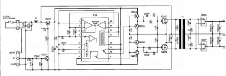
i want try this one
is it ok in shematic?
Attachments
Last edited:
I think it looks fine.
I haven't translated the PDF yet but I believe it says something about using 4 FET's for a 300 watt range.
This I would consider doing as a safety measure anyhow.
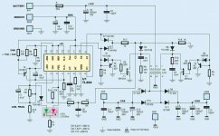
In order to get the voltage range you want you just need to adjust the secondary winding turns is all because the voltage correction feedback is taken off of the primary side.
I you can add a trimmer Pot. in that loop for a voltage adjustment as well.
I will look over the schematic and let you know know were it should go.
jer
I haven't translated the PDF yet but I believe it says something about using 4 FET's for a 300 watt range.
This I would consider doing as a safety measure anyhow.
In order to get the voltage range you want you just need to adjust the secondary winding turns is all because the voltage correction feedback is taken off of the primary side.
I you can add a trimmer Pot. in that loop for a voltage adjustment as well.
I will look over the schematic and let you know know were it should go.
jer
I think it looks fine.
I haven't translated the PDF yet but I believe it says something about using 4 FET's for a 300 watt range.
This I would consider doing as a safety measure anyhow.
In order to get the voltage range you want you just need to adjust the secondary winding turns is all because the voltage correction feedback is taken off of the primary side.
I you can add a trimmer Pot. in that loop for a voltage adjustment as well.
I will look over the schematic and let you know know were it should go.
jer
Hi
please show me in photo weher can i ad a trimmer pot to adjustment voltage.
that have a pot. what is that?
thanks
Yes, You can use them if you like.
As long as you use at least fast types you are okay.
I used regular diodes in my HV Supply at at over 100khz and got away with it but I do suffer much more losses due to the slow turn off time.
I used them because it was all I had and I found that they did work for my application as I don't need to pull any heavy currents from the supply.
Had I any UF4007's I would gladly have used them.
Yes, I will go over the circuit and determine the trimmer for you.
Jer
Yes ,those are very nice diodes !!
http://www.st.com/internet/com/TECHNICAL_RESOURCES/TECHNICAL_LITERATURE/DATASHEET/CD00000746.pdf
However this one is rated at 45v but should be quite suitable for your application at 25v,
http://ixdev.ixys.com/DataSheet/l131.pdf
jer
http://www.st.com/internet/com/TECHNICAL_RESOURCES/TECHNICAL_LITERATURE/DATASHEET/CD00000746.pdf
However this one is rated at 45v but should be quite suitable for your application at 25v,
http://ixdev.ixys.com/DataSheet/l131.pdf
jer
Last edited:
- Status
- This old topic is closed. If you want to reopen this topic, contact a moderator using the "Report Post" button.
- Home
- Amplifiers
- Power Supplies
- smps for car audio with TL494