Take it easy, 99% is a wet dream I suppose
Well... Depends how you measure? Right?
The 99 is achieved without the input and output inductors.
With them the efficiency is down to about 95%.
Could rethink the inductors a bit, but then again Im quite happy with the thing already as it is.
Transformers are 6 turns primary made from copper foil 0.125mm thick x 16mm wide...
Secondaries 2x 0.9mm 16 turns...
Flat out power is 560W but I would blow the diodes pretty soon (MUR1560) with that, so adjusted down to 440W only...
With 560W output power a 50A fuse holds - nice...
FETs are the suggested IRF3703. Their advantage is the fast switch off, which results in to close 50/50 duty cycle...
37A at 12V makes 440W, right?
It takes as little as 3.2miliohms through Mosfets, transformer primary, PCB traces, inductors and cabling together to loose 1%, ie. 4.4W at 37A. It is very tough to achieve.
Rectifer diodes drop a volt or so, that's another percent at 100VDC secondary and two percent at 50VDC secondary.
Even a primary capacitor can be a bottleneck, a very good 10000uF cap will have like 20miliohms, draw several amperes through it and you loose another fraction of a watt, a watt or two.
Switching losses don't usually dominate at below 50kHz.
Ferrite cores are also pretty lossy unless you run them at <100mT.
Don't worry, 95% is already a very good result, I wasn't able to achieve that high with 12V/600W push-pull with buffered IRFB3004, tight tape (foil) wound primaries, HV secondaries, sendust chokes and so on.
How is push-pull not inherently more efficient here?
Ofcourse it is. Just put in a bigger core and there you have it.
I myself prefer fullbridge because of the ridiculously simple transformer. No need to worry about perfectly symmetrical primaries with just a couple of turns around the core.
12V SMPS
Absolutely! An ETD39 core + IRFZ44N devices has the potential of a great supply. But, it takes a lot more than that. It depends a lot on the core material too. Do you know the core material?
There's no PCB because we've been discussing theory, simulations, and industry standards. We're not at the actual assembly of his 575W (now 400W) supply. I posted a pic of my 500W supply just as a reference of one way it can be built.
Keep watching for more details. Plus, read through this and other SMPS threads so you can begin designing your supply!
hi guys
sorrry for my bad english
i have ETD39 and IRFZ44N
can i use that?
i did not see any pcb in this topic.!!
please help me friends
thanks
Absolutely! An ETD39 core + IRFZ44N devices has the potential of a great supply. But, it takes a lot more than that. It depends a lot on the core material too. Do you know the core material?
There's no PCB because we've been discussing theory, simulations, and industry standards. We're not at the actual assembly of his 575W (now 400W) supply. I posted a pic of my 500W supply just as a reference of one way it can be built.
Keep watching for more details. Plus, read through this and other SMPS threads so you can begin designing your supply!
Thanks for your reply and sorry for my bad english.
I am basic in electronic and i do not have a oscop to make a good smps.
I buy the 800 number of TL494 and 1000 number of IRFZ44N and 300 number of ETD39 in very low price in my city.
He quite him job and sele all of that things to me with half of price.
I want to creat smps with that beacuse i have that.
Sorry for my bad english egain.
Please give me a chance with that parts.
Thank you engineers.
You should attach the file to your post
You can attach the pdf you linked in your post. It is nicer to do that instead of sending DIY-ers to a sharing site.
Thanks
You can attach the pdf you linked in your post. It is nicer to do that instead of sending DIY-ers to a sharing site.
Thanks
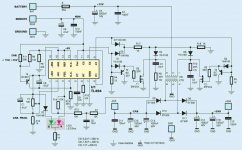
Schematic of my 500W SMPS
I put together a schematic of my SMPS. It's attached.
Take a look and see if it offers any help towards designing your SMPS. It's a pretty basic, unregulated supply that's very common in high-end car audio.
This exact topology could be scaled up and down by simply modifying the transformer, switch devices, caps, switching diodes, etc.
Enjoy!
Attachments
sorryYou can attach the pdf you linked in your post. It is nicer to do that instead of sending DIY-ers to a sharing site.
Thanks

i do not how?
Attachments
is this okYou can attach the pdf you linked in your post. It is nicer to do that instead of sending DIY-ers to a sharing site.
Thanks
?wich one of this shematic can help me?I put together a schematic of my SMPS. It's attached.
Take a look and see if it offers any help towards designing your SMPS. It's a pretty basic, unregulated supply that's very common in high-end car audio.
This exact topology could be scaled up and down by simply modifying the transformer, switch devices, caps, switching diodes, etc.
Enjoy!
can i recive + - 32VDC 15A ?
please help to do that with TL494 and IRFZ44N.
i can buy another core like ETD 54
is this core good for 850w?
Attachments

Hadighorbani - instead of looking for a schematic to fill your exact needs and copying it, you will instead most likely have to modify an existing design to fit your needs. And to do that, you'll have to study and learn the basics of switch-mode-power-supplies (SMPS). Check out Switched-mode power supply - Wikipedia, the free encyclopedia for some good information, plus Google SMPS design, topology, components, etc. Next, do a lot of research on this forum for information on specific projects people have built. Lastly, after you have made some progress with your knowledge and have decided exactly what you want to build, start a thread on this forum detailing your project and progress asking for feedback from others. That way you can build your SMPS and get lots of help and support from some exceptionally talented people. Just a suggestion.
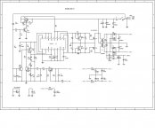
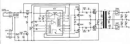
By the way, look closely at the three schematics you posted. Right away you should start seeing similarities in the designs, topologies, and components. This is a first step to understanding them...
By the way, look closely at the three schematics you posted. Right away you should start seeing similarities in the designs, topologies, and components. This is a first step to understanding them...
thanks dear friends
Thanks friends
I try this one to make it.
Thanks for your helping
HiHadighorbani - instead of looking for a schematic to fill your exact needs and copying it, you will instead most likely have to modify an existing design to fit your needs. And to do that, you'll have to study and learn the basics of switch-mode-power-supplies (SMPS). Check out Switched-mode power supply - Wikipedia, the free encyclopedia for some good information, plus Google SMPS design, topology, components, etc. Next, do a lot of research on this forum for information on specific projects people have built. Lastly, after you have made some progress with your knowledge and have decided exactly what you want to build, start a thread on this forum detailing your project and progress asking for feedback from others. That way you can build your SMPS and get lots of help and support from some exceptionally talented people. Just a suggestion.
By the way, look closely at the three schematics you posted. Right away you should start seeing similarities in the designs, topologies, and components. This is a first step to understanding them...
Thanks friends
I try this one to make it.
Thanks for your helping
I put together a schematic of my SMPS. It's attached.
Take a look and see if it offers any help towards designing your SMPS. It's a pretty basic, unregulated supply that's very common in high-end car audio.
This exact topology could be scaled up and down by simply modifying the transformer, switch devices, caps, switching diodes, etc.
Enjoy!
hi
are you tested this smps by own?
is it good?
can i use ee55 core for 500 watt in your smps?
can i reaplace irfz44n mosfets with irfz42?
what about r1 to r6?
can you calculate R1 to R6 for irfz44n please?
thanks
- Status
- This old topic is closed. If you want to reopen this topic, contact a moderator using the "Report Post" button.
- Home
- Amplifiers
- Power Supplies
- 576W SMPS for car audio amplifier