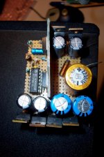
For those wanting to enjoy the Circlophone (or any other conventional amplifier) elsewhere than at home, here is a simple and economical solution.
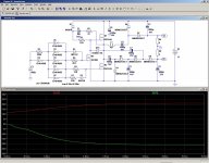
It is a simple, non-regulated charge-pump converter.
The components are cheap and universally available, yet the performances are decent (η > 90%).
The continuous output power is ~175W with adequate heatsinking, which is more than sufficient for a 2 x 80W amplifier (used for actual musical signals, obviously).
It could also serve as a base for other projects: a mobile 0->+/-20V 3A lab supply for example.
The oscillation frequency is ~22KHz, just outside the audio range.
For automotive applications, a ruggedized input filter + fusing is recommended.
At the amplifier level, additional decoupling is also recommended.
Needless to say, all the capacitors must be low esr.
Attachments
Last edited:
MF Supercharger - Comparable to the circuit topology here?
Basic Idea is very interesting. Unfortunately filed by "Power supplies" instead "Solid State".
what about the commercial product in this kind from Musical Fidelity?
here several URLs:
Musical Fidelity 550K Supercharger review from the experts at whathifi.com
http://thehifisite.com/musical-fidelity-550k-supercharger/
Review | MUSICAL FIDELITY 550K SUPERCHARGERS Innovative amplifiers add plenty of power, plus so much more They fly in the face of purism, says Andrew Everard, but there's no denying the benefits they bring | Page137 - December2007 - Gramophone Arch
Recensie MF_Superchargers
Musical Fidelity Supercharger 550K: STEREO | Zeitschrift für HiFi, High End & Musik
Musical Fidelity 550K Supercharger - Spezifikationen Musical Fidelity 550K Supercharger Vorverstärker | Stassen Hifi
http://www.diyaudio.com/forums/tubes-valves/155619-driver-musical-fidelity-550k.html
Last edited:
It is no more than a power supply booster/adapter without great originality.Basic Idea is very interesting. Unfortunately filed by "Power supplies" instead "Solid State".
It allows you to operate a classic living-room class AB amplifier from a 12V source, and it does so cheaply, simply and reliably.
No rocket science, but useful and effective.
Elvee, i love the DIY-friendlyness of your ideas. They work and don't need mysterious requirements while keeping it simple
")
The inductor is not even required: it reduces the peak currents in in the MOSfets, and equalizes the V+ and V- voltages under load, but the circuit will work without.Very Cool and doesn't require a huge inductor !!!
Very interesting !
I have often wondered if such a topology might work.
I have done similar circuits using multipliers in simulations, But I have not yet built one.
I noticed the large valued capacitors in the multiplier stage and this is the key to getting a high current output as well as the higher switching frequency.
I was thinking that the inductor was used as it is in a boost converter.
As I was trying to figure out how to design a high current boost converter at one point to power some chip amps off of a car battery in a vehicle.
It was based on a circuit on page 2 of project 105 of Rod Elliot's website, But I never got any farther than the simulations.
Great Work !!!!
jer
Needless to say that all the big E-lytics must be low esr, otherwise they will blow up in a matter of minutes.I noticed the large valued capacitors in the multiplier stage and this is the key to getting a high current output as well as the higher switching frequency.
You are free to use any square wave generator for this purpose. The 40106 is advantageous, because it is as cheap as a 555, consumes almost no power and has an inherent ~50% duty cycle, all of that with a minimal number of external components, but there are hundreds of alternative solutions.Hello, it's a really nice circuit. I wonder if I could use something like 555 generator to drive FETs?
Here it is, copied from my HD (remove the .txt). You can find the originals at the yahoo! LTspice group.Also, could you please upload CD40106B.asy file so I can play with it in Spice?
Best regards, Vic.
I have also included the CD4000 lib with the model (also available from the same source)
Attachments
Yes, at the moment I am simulating it in TINA-TI with opamp based square wave generator. Would there be any advantages to increase frequency? I am probably gonna breadboard it, but atm I am just playing around in sim. I am quite unsure what is purpose of 10uF cap/22R resistor there. (C1/R2) Could you explain it, please?
Thank you for spice models and everything.
Cheers, Vic.
Thank you for spice models and everything.
Cheers, Vic.
Yes, the usual ones: smaller reactive components, lower ripple, etc, all of that is well documented.Would there be any advantages to increase frequency?
Difficulties associated with increased frequency are as well documented, like increased losses. You have to choose your evil. Lower frequencies are generally more tolerant on components and less demanding on layout, etc, but require more physical space (moderate), which is why I have chosen this path.
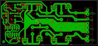
It provides a bootstrapped supply to the gate of M1, and is therefore essential for a decent efficiency when using NMOS only.I am probably gonna breadboard it, but atm I am just playing around in sim. I am quite unsure what is purpose of 10uF cap/22R resistor there. (C1/R2) Could you explain it, please?
PS
Breadboarding is certainly possible, but you have to think carefully at how you are going to lay out your circuit to avoid common inductive loops, the effect of some contact resistances, etc
I have simulated the circuit at 14.4v (automotive electrical system average with alternator on), and it outputs between 24-25v per rail into 4 ohms. Very nice.
Regarding the dual schottky rectifiers: does anyone recommend a substitution for these? The specified part is a dual diode in one package, and the circuit does not make use of them correctly (common cathode connection internal to the part)... Unless we are meant to connect them in parallel, which is not usually done with diodes, as they won't share current equally.
Regarding the dual schottky rectifiers: does anyone recommend a substitution for these? The specified part is a dual diode in one package, and the circuit does not make use of them correctly (common cathode connection internal to the part)... Unless we are meant to connect them in parallel, which is not usually done with diodes, as they won't share current equally.
Yet that is exactly what I did. Of course, I have heaps of them, and this probably explains why I used and specified them in this case and in this way (it also brings the forward drop down a little), but you are perfectly free to use any other suitable component you have in store, paralleled or not. Perhaps you don't need all the power, and you can get away with smaller devices, or on the contrary you need to power a multichannel amp and could use 40A size. That's up to you.Regarding the dual schottky rectifiers: does anyone recommend a substitution for these? The specified part is a dual diode in one package, and the circuit does not make use of them correctly (common cathode connection internal to the part)... Unless we are meant to connect them in parallel, which is not usually done with diodes, as they won't share current equally.
Even non-schottky diodes would be usable, but the voltage loss and dissipation would be severe.
Similarly, the IRFZ44 choice could be challenged: there are now much better devices available, but these are cheap and widely available, and that is often an important factor for me.
Elvee, thank you for your many contributions to this forum
I am attracted to this charge pump converter because it does not require expensive (and/ or tedious to wind) magnetics, yet still provides a dual rail output. I will try to find some fast diodes that can handle the current, maybe MUR series... I will report my results.
Cheap and widely available are noble criteria, IMHO; we should be using what we can instead of throwing things away.
Last edited:
It will work of course, but the output voltages will be 1 or 2V lower, and the efficiency will also be slightly degraded (which means you will need larger heatsinks)I am attracted to this charge pump converter because it does not require expensive (and/ or tedious to wind) magnetics, yet still provides a dual rail output. I will try to find some fast diodes that can handle the current, maybe MUR series....
- Status
- This old topic is closed. If you want to reopen this topic, contact a moderator using the "Report Post" button.
- Home
- Amplifiers
- Power Supplies
- Boostor, an ideal companion for a Circlophone on the move