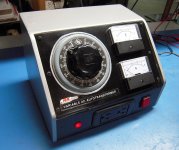
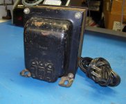
Don't be shocked, but I have an ancient Stancor P-6415 isolation transformer that I really should be using on the bench. It has a 2 wire, ungrounded plug. Should I add a grounded cord? If so, would the ground wire connect to the case?
And does it make a difference whether a Variac is plugged into it or vice-versa?
And does it make a difference whether a Variac is plugged into it or vice-versa?
the whole purpose of an isolation transformer is so that you can "float" whatever you're working on.
you should be able to grab either side of the 120vac line after the isolation transformer and NOT get shocked.
if you ground the output of an isolation transformer it pretty much defeats the purpose of having one.
you should be able to grab either side of the 120vac line after the isolation transformer and NOT get shocked.
if you ground the output of an isolation transformer it pretty much defeats the purpose of having one.
The Earth connection is needed to blow the mains fuse if the transformer or it's connections become faulty.
If you can "see" that the isolation transformer is not faulty and cannot send mains voltage downstream to the following equipment then one does not need the Earth connection.
BUT,
that is a big risk if something goes wrong that you can't see !
If you can "see" that the isolation transformer is not faulty and cannot send mains voltage downstream to the following equipment then one does not need the Earth connection.
BUT,
that is a big risk if something goes wrong that you can't see !
Grounding, or better: connecting protective earth (PE) (aka: safety earth) to the case of the transformer would not change the fact that the output is isolated from the input. It's only the mains part (L and N) that needs to be isolated and of course PE would only be connected to casings. Hence the reason why many isolation transformers have PE available on both in- and outputs.
This wiki article states that a grounded elctrostatic shield inside an isolation transformer prevents capacitive coupling between primary and secondary windings.
The schematics symbol for isolation transformer should also give a clue (first image).
Look at page 22 for type e of this pdf. Your transformer has an electrostatic shield which, according to the document, is "grounded to the core internally".
So yes, I would connect the case of the transformer to PE.
If your variac is an autotransformer, it is not isolated (second image) and I would use it behind the isolation transformer. If your variac is truly isolated (look for the two circle image on the case, similar to the third image), then the isolation transformer would not be needed on that variac.
Edit: if you're unsure if the variac has fully isolated windings, always assume for safety reasons that it hasn't.
Attachments


Last edited:
Agreed for testing purposes the output of the isolation transformer should be left floating. But beware, simultaneously touching live (L) and neutral (N) wires at the isolated end of the transformer remains just as dangerous! Only the (more common) mistake of touching L and e.g. case is not dangerous anymore.
Having said that, there are situations in which it is necessary to make an isolated supply act as a normal one. PE and N are interconnected on the secondary side (e.g. on a boat that gets an isolated power supply from shore to prevent electrolytic corrosion, see image). PE on primare side and secondary side are NOT interconnected, though. I didn't make that clear in my first post.
But for testing purposes, only use L and N to power a device, do not connect PE!
Attachments
Having or not having a third ground wire is irrelevant to the operation of the isolation transformer, as far as isolating goes. Newer models have the ground connected to a shield within the unit, to head off any capacitive coupling between the primary and secondary windings. If the windings in yours were to fail badly enough that they would be exposed to the case, then the current would have most likely blown the main breaker anyway - as the neutral (white wire) on the primary side AC line is already connected to earth/ground, at the breaker box.
If it makes you feel better to add a 3-wire cord and connect it to the case, go right ahead. But I would be more worried about the safety of old iron/copper in general - as this unit may not have an electrostatic shield built-it, or may have been modified by someone else, that felt it more bothersome to change the outlets in their house to 3-prong.
In reference to the ground passing all the way through the unit - this defeats nothing, as most AC transformers (with the exception of variacs) are "isolation" transformers. They just step up or step down, but the ground is still there, and technically bypasses the TF altogether. If it were me, I'd at least pop the covers off and take a peak, and secondly, it's your safety in question - when in doubt, throw it out.
As far as the variac goes, I haven't used mine since discovering the "dim bulb". Most will say it does not matter, but I prefer mine connected after the iso - just because the only thing on the primary side, is the primary itself - every switch, button, knob, and dial after that, is isolated.
Does yours have a single cord connected to the secondary, or 3 outlets on the case? i.e. 110, 115, 125...
Last edited:
- as this unit may not have an electrostatic shield built-it
It does (see post #5).
It does (see post #5).
OK... then he still should be able to connect it to a grounded 3-wire cord, as well as 3-wire secondary, but it should already have 3 taps on the case.
Last edited:
if you ground the output of an isolation transformer it pretty much defeats the purpose of having one.
99% of the transformers on this planet are isolating types, and 99% of those are in fact grounded on their secondary. The term 'isolating' is generally unnecessary; it is a given. Any type of autotransformer or variac is understood to have a common connection, and those become the exception to the rule. There are two common options for applying to the secondary:
1. Float the entire secondary, which enables flexibility with what is being powered. We can float our oscilloscope to make floating measurements (with great caution) or we can use it to power medical equipment to prevent shocking the patient. Generally, floating systems are to be avoided, code discourages it, and IEEE does not recommend it. They are only designed for a few specific applications. I see DIY'ers floating it as a band-aid to a larger grounding problem, so the claim is that floating is the way to go (since it 'solved' their problem). This is unfortunate.
2. Ground the secondary. The preferred method for non-testing purposes. The purpose of the isolating transformer has STILL performed its function; it has galvanically isolated the primary system from the secondary system, and provided a separately derived system. It will be very effective in eliminating ground loops. Misunderstood in great measure on this forum, unfortunately.
The Primary or Input side should be grounded.
Do not EVER ground the primary side. The primary system is grounded back at the panel, and that should be the ONLY place it is grounded. Basic code requirement. You can take a third wire and 'bond' the case, shield, and core, but this is altogether different than grounding the primary winding.
These are some great responses! Apparently, there are some differences of opinion.
Yes, this transformer has 3 secondary outlets. But since I'll be using an autotransformer along with it, the 125v outlet will be the only one used. I acquired this transformer in 1981 and it looked old at that time. but it doesn't appear like it's ever been opened.
My custom made Variac has a ground wire connected to the transformer shell and the receptacles. If I use an ungrounded isolation transformer before it, then I'll need to cheat the ground pin. Is this correct?
Attachments
Can you be specific in what you intend to do with this? If it's for testing and playing around with recent builds on the bench, then a floating output is fine. If you want to use it in a semi-permanent installation, there should be a ground reference.
Not sure what you mean by cheating the ground pin. Every enclosure and core should be grounded by means of the 3rd prong when it's available. Whether or not the transformer secondaries are bonded is a separate issue, and the one being debated. Maybe this is deviating from your original request, of which I would apologize.
Not sure what you mean by cheating the ground pin. Every enclosure and core should be grounded by means of the 3rd prong when it's available. Whether or not the transformer secondaries are bonded is a separate issue, and the one being debated. Maybe this is deviating from your original request, of which I would apologize.
I'll be using it for testing and troubleshooting vintage tube radios and audio components, which I've been doing for 5 years without a safety net.
I rekon I've pushed my luck a little long enough.
So pardon me, but I need to clearly understand two things; do I use this transformer upstream or downstream of the variac and do I add a ground connection to its case?
I rekon I've pushed my luck a little long enough.
So pardon me, but I need to clearly understand two things; do I use this transformer upstream or downstream of the variac and do I add a ground connection to its case?
You don't need to cheat anything - the 3rd prong ground contributes little to a working circuit, other than than a measure of safety, and where the iso is concerned, a connection to ground for the shielding.
However, what you do need to do, is verify the connections internally and externally of both devices, before joining them together as a bench tool. Doing things without a safety net, and knowing it, is entirely different from not having one, and thinking that you do.
Work out schematics for both devices - then decide on which is better, first or last. It would also probably be a good idea to figure out which wire tap, out of the 3, is the 1:1 tap as well, to simplify things a bit.
do I use this transformer upstream or downstream of the variac and do I add a ground connection to its case?
you can install it up or down, but I would suggest upstream to get the optimal xfmr utilization.
Grounding cases and cores is always a good thing
Agreed for testing purposes the output of the isolation transformer should be left floating. But beware, simultaneously touching live (L) and neutral (N) wires at the isolated end of the transformer remains just as dangerous! Only the (more common) mistake of touching L and e.g. case is not dangerous anymore.
Having said that, there are situations in which it is necessary to make an isolated supply act as a normal one. PE and N are interconnected on the secondary side (e.g. on a boat that gets an isolated power supply from shore to prevent electrolytic corrosion, see image). PE on primare side and secondary side are NOT interconnected, though. I didn't make that clear in my first post.
But for testing purposes, only use L and N to power a device, do not connect PE!
Sorry to revive an old thread, but I wanted to clear a doubt. My isolation transformer is connected to the wall outlet (3 prong), then its output is fed to a voltage stabiliser which then feeds to my gear. So the correct way is to just connect the IT to the phase & neutral of the wall outlet & connect the earth only to its chassis? So the stabiliser or components that come after the IT are not connected to Earth even on their chassis? All my power cords are shielded, so is it ok to not ground the shield then???
- Status
- This old topic is closed. If you want to reopen this topic, contact a moderator using the "Report Post" button.
- Home
- Amplifiers
- Power Supplies
- Isolation Transformer