Hi everyone,
I would like to build battery power supply for my new M2Tech HiFace Evo USB -> S/PDIF converter.
Input from 12VDC battery, output 9V. Converter accept 5-11V.
I've done some research and this is what I draw.
Now question:
- I the schematic correct?
- Do I need C1 and C2 caps if DC is on input? I guess that caps are for additional filtration of AC, some switch mode, judging by 100uF.
Please hep to beginner.
An externally hosted image should be here but it was not working when we last tested it.
According to the data sheet
http://www.st.com/internet/com/TECHNICAL_RESOURCES/TECHNICAL_LITERATURE/DATASHEET/CD00000449.pdf
scroll down to page 10 for the 78s09; the minimum input voltage for 9V output is 12V. If you eliminate D1 (not necessary if it is powered from a DC source like your 12V battery) and change C1 to .33uF and C2 to .1uF as in the examples given in the data sheet (page 8 figure 5) it should work until your battery voltage drops below 12V. Perhaps you should look for a low drop out regulator.
Last edited:
Or you could do something like this. This will give you 9.3V if you are drawing 2A of current and 10.2V with no load. This fits within your voltage range for your S/PDIF converter. 5-11V. The capacitor smothes any load variation caused by your S/PDIF converter.
Attachments
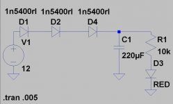
Your schematic is correct. The 0.5W rating for the LED ballast resistor is overkill - the dissipation there will be minimal (~50mW) so any 1k resistor will work.
RJM1 is right about the capacitors and that the Operating input voltage spec for the 78S09 is stated as 12V, but if you look above that their Output voltage test conditions for Vo are shown as Io = 1 A, Vi = 11 V. I think their 12V spec is derived from the graph on page 22, "Dropout voltage vs. junction temperature." In that graph you can see that at a lower current (and I'm going by a Evo current of ~150mA), the dropout voltage is less, more like 1.5V.
I'm mentioning all this mainly with an idea that you have the parts in hand. If you don't, a LDO may be a better idea. You want to insure that your battery can drop to 10.5-11 volts and still provide enough for a regulated output.
edit: I see that ~150mA is idle current. TBC...
Last edited:
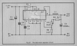
The humble TL497
If you want to go a little bit more advanced you can always use the humble TL497.
This will operate from between 4.5 and 15V volts and give you a stable output voltage.
You simply adjust VR1 and R2 and R3 to give you 1.2V at pin 1.
L1 doesn't need to be anything special just as many turns as you can get on a salvaged ferrite ring or pot core. (Unless you are after higher current output - in this guise it will output up to 500mA).
Although the article states that using this circuit above 6V is pointless, it is assuming that the input voltage never drops below the drop-out voltage of a series regulator.
This circuit has been used in many guises to extend the battery life of some toys and other applications.
Attachments
Last edited:
The TL497 is pretty commonly available for next to nothing.
TL497ACN VOLTAGE CONVERTER 14 PIN DUAL IN LINE | eBay
TL497ACN VOLTAGE CONVERTER 14 PIN DUAL IN LINE | eBay
What bout this variable one?
I've even designed my very 1st PCT for that one. What you reckon?
An externally hosted image should be here but it was not working when we last tested it.
I've even designed my very 1st PCT for that one. What you reckon?
An externally hosted image should be here but it was not working when we last tested it.
Teti, there is one thing I don't get - you've got a relatively low noise battery, why do you add a rather noisy device after it? There are several features you should want from your new regulator - low noise, low dropout and high efficiency. You are not concerned with PSRR anymore (that is the only advantage of LM317).
So - how about LT1963?
You could even get something like that from ebay... Unless you are building it for fun.
VERY LOW NOISE <40?V Adjustable Voltage Regulator Board, 3 Amp(Max.) | eBay
Tomáš
So - how about LT1963?
You could even get something like that from ebay... Unless you are building it for fun.
VERY LOW NOISE <40?V Adjustable Voltage Regulator Board, 3 Amp(Max.) | eBay
Tomáš
Teti, there is one thing I don't get - you've got a relatively low noise battery, why do you add a rather noisy device after it? There are several features you should want from your new regulator - low noise, low dropout and high efficiency. You are not concerned with PSRR anymore (that is the only advantage of LM317).
So - how about LT1963?
You could even get something like that from ebay... Unless you are building it for fun.
VERY LOW NOISE <40?V Adjustable Voltage Regulator Board, 3 Amp(Max.) | eBay
Tomáš
Tom are you from Czech?
I was fiddling with DIY because I couldn't find any proper diy kit on eBay.
You suggestion will be probably much better.
Yes, I am.
I had to solve a similar problem recently - 5V power supply for USB/i2s device. This was my solution - The σ11 Regulated Power Supply - with a toroidal transformer. Not a big fan of batteries...
I had to solve a similar problem recently - 5V power supply for USB/i2s device. This was my solution - The σ11 Regulated Power Supply - with a toroidal transformer. Not a big fan of batteries...
What bout this variable one?
I thought the fixed voltage regs were of better quality
- Status
- This old topic is closed. If you want to reopen this topic, contact a moderator using the "Report Post" button.
- Home
- Amplifiers
- Power Supplies
- 9VDC battery powered power supply