The project is op-amp based, so I investigated if there was reason to build a discrete operational amplifier, but finally I concluded that it is better to use a monolithic OA, such as AD797, AD825, OPA627, OPA132 or so.
Have you read Jung's article dated 2000? The AD825 is the preferred OPA for voltage reference in its regulators.
I have little doubt that at least the requirements for analogue circuit regulators are very different from those meant to power digital circuits.
I agree 100%.
I agree with you that different circuits requires different power supplies.
Btw if you had an ideal supply you could use it either for analogue than digital circuits. Obviously ideal supply does not exists and I have no claim to build it.
It can be done but it would be a waste of money.
I prefer to have several independent PSU than to connect several lines to a SOTA one.
Have you read Jung's article dated 2000? The AD825 is the preferred OPA for voltage reference in its regulators.
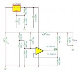
I have read Jung's article, but I'm designing a series regulator operating in a different mode. As you can see in the schematics I do not use the opamp to modulate a current source like in Jung Super Regulator, rather the pass transistor is modulated directly from opamp error signal.
BTW I choose LT1028 that has superior performance than AD825, IMHO. LT1028 shows impressive electrical characteristics:
input noise voltage: 1nV/sqrt(Hz)
PSSR: 133 dB
GBW: 75 MHz
Only slew rate is lower than AD825, but don't forget that a shunt regulator follows the series regulator in my design, so I think relatively slowly opamp such LT1028 (11V/us) do not affect the final regulation because shunt section improves transient response.
hmm, so the opa637 is for higher voltage versions yes? its really not very happy with low gain in my experience it needs to be 3-4x or above, certainly not unity
Maybe there's another way to implement OPA350 in any case, low and high voltage, let opamp operate always at low voltage like in the attached schematic.
Attachments
I have read Jung's article, but I'm designing a series regulator operating in a different mode. As you can see in the schematics I do not use the opamp to modulate a current source like in Jung Super Regulator, rather the pass transistor is modulated directly from opamp error signal.
BTW I choose LT1028 that has superior performance than AD825, IMHO. LT1028 shows impressive electrical characteristics:
input noise voltage: 1nV/sqrt(Hz)
PSSR: 133 dB
GBW: 75 MHz
Only slew rate is lower than AD825, but don't forget that a shunt regulator follows the series regulator in my design, so I think relatively slowly opamp such LT1028 (11V/us) do not affect the final regulation because shunt section improves transient response.
I hadnt seen the schematics when I posted. Your circuit looks good and does not seem over-expensive for a high quality digital PSU. Glad you ditched the inductors
") I'm looking forward to the PCB.
I'm looking forward to the PCB.BTW, are the diodes schottky?
I hadnt seen the schematics when I posted. Your circuit looks good and does not seem over-expensive for a high quality digital PSU. Glad you ditched the inductors
BTW, are the diodes schottky?
Diodes are FRED epitaxial with 35 ns trr.
BTW you can use shottky like SB3100, MBR3100 or so.
Question
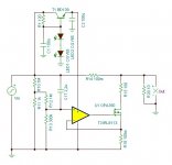
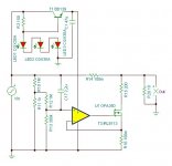
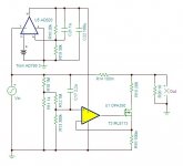
In order to use OPA350 also in regulator that output a voltage greater than 5.5V we have to reduce its power supply voltage to 4/5V.
After some simulations I found two way as in the attacched schematics: first simply with 3 red LEDs, the second more complex with TL431.
I would like to know which one you favor, or if you have any other suggestion.
Thanks all
Andrea
Attachments
In order to use OPA350 also in regulator that output a voltage greater than 5.5V we have to reduce its power supply voltage to 4/5V.
After some simulations I found two way as in the attacched schematics: first simply with 3 red LEDs, the second more complex with TL431.
I would like to know which one you favor, or if you have any other suggestion.
Thanks all
Andrea
TL431 for the thermal stability of its bandgap reference.
Tony
Gootee,
looks like they have not read your two posts. They are still worried about the opamps.
Good decoupling at the load will reduce the slew rate of the step response on the supply rails and that reduces the need for ultra high speed opamps. They don't seem to see the connection.
looks like they have not read your two posts. They are still worried about the opamps.
Good decoupling at the load will reduce the slew rate of the step response on the supply rails and that reduces the need for ultra high speed opamps. They don't seem to see the connection.
In order to use OPA350 also in regulator that output a voltage greater than 5.5V we have to reduce its power supply voltage to 4/5V.
After some simulations I found two way as in the attacched schematics: first simply with 3 red LEDs, the second more complex with TL431.
I would like to know which one you favor, or if you have any other suggestion.
Thanks all
Andrea
I would not use such a simple emitter follower. I would use a 3-pin 5V regulator for the opamp supply: more accurate, lower impedance, better rejection. With an electrolytic on its output.
jan didden
I would not use such a simple emitter follower. I would use a 3-pin 5V regulator for the opamp supply: more accurate, lower impedance, better rejection. With an electrolytic on its output.
jan didden
So I have to ask... You are already using a part that has 90dB CMRR, how much quieter do you need to be?
This isn't a slam, I'm just curious.
Tony
Two more options
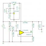
There are two more options to set operating voltage of the OPA350 around
5V.
The first option uses an AD820 opamp as series regulator to supply directly OPA350 taking voltage reference from AD780.
The second option, the simplest, use one more LT1085 regulator.
In any case for 5V output regulator this section should be omitted, and the OPA350 should be supplied directly form series regulator output.
Attachments
Gootee,
looks like they have not read your two posts. They are still worried about the opamps.
Good decoupling at the load will reduce the slew rate of the step response on the supply rails and that reduces the need for ultra high speed opamps. They don't seem to see the connection.
AndrewT,
I actually hadn't thought of it that way, either. But you have made what could be a very good point.
I was originally only thinking that a more-realistic simulation scenario should be used, in order to give a more-realistic estimate of performance, to possibly enable better requirements and performance metrics to be defined, which might result in a design that would perform better in the real application.
I assumed that adding a simulated load scenario might expose some deficiencies that could require design improvements. But as you have pointed out, it might actually allow the performance requirements to be relaxed, somewhat.
Cheers,
Tom
There are two more options to set operating voltage of the OPA350 around
5V.
The first option uses an AD820 opamp as series regulator to supply directly OPA350 taking voltage reference from AD780.
The second option, the simplest, use one more LT1085 regulator.
In any case for 5V output regulator this section should be omitted, and the OPA350 should be supplied directly form series regulator output.
Ooops.. there is an error in the AD820 schematic in the previous post: AD820 output connected to positive rail.
The following is the right schematic.
Attachments
Ready to prototyping
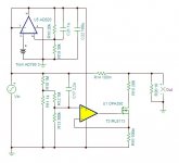
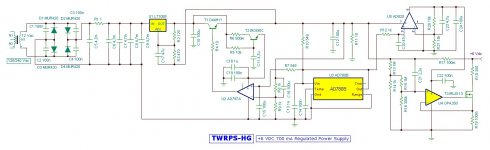
Follows the revised schematic ready to build a prototype.
Some changes:
- AD797 op amp in series regulation stage
- AD780 now works in shunt mode
- AD820 supplies fixed 5V for OPA350, so it could be used at any regulator output voltage
Comments are wellcome
Andrea
Follows the revised schematic ready to build a prototype.
Some changes:
- AD797 op amp in series regulation stage
- AD780 now works in shunt mode
- AD820 supplies fixed 5V for OPA350, so it could be used at any regulator output voltage
Comments are wellcome
Andrea
Attachments
Although it's true that high frequencies should be handled by (local) by-pass capacitors, I would rather avoid high feedback designs (thus Op-Amps) and would use simpler, faster (wide-bandwidth), all-discrete designs instead.
A simple integrated pre-regulator shall be more than enough to kill ripple and keep the voltage stable at the source. I don't quite see the need for a second cascaded one. To get better filtering, instead of a second series regulator I would rather use a CCS between the series (pre-)regulator and the output shunt reg (in parallel with plenty of by-pass capacitance).
The CCS very high series impedance followed by the very low shunt impedance of the shunt reg & by-pass caps forms a voltage divider (RC-like filter) which is extremely effective in cutting away any kind of noise coming from the previous stages (as well as blocking any noise from the load trying to travel in the opposite direction). Add RF-chokes and/or ferrite beads in series with the CCS to stop any HF/RF noise too.
N.B.: also for the CCSs you must use simple, wide-bandwidth, all-discrete designs. Do not use op-amp based CCSs such as a CCS-connected integrated regulator!
P.S.: use only Schottky barrier diodes for the rectifier! That's the only kind of diodes (besides vacuum tubes...) which do not suffer from reverse-recovery and associated noise (having only one type of carriers, there's nothing to recombine).
Another often neglected problem is the rectification noise due to the current peaks in the PT/rectifier/filter capacitors circuit. That's a huge source of wide-bandwidth noise which is radiated just about everywhere (and possibly conducted, too).
The solution is to slow down and drastically limit the amplitude of those current peaks. To do so, again I'd use a simple CCS (such as a depletion-mode FET or a couple of BJTs "back-to-back") in series between the diodes and the first cap. That will work sort of like an inductive-input (LC) filter, but without the many problems associated with the "swinging choke" (of course, as for the LC type filters, you'll need a higher voltage on the PT secondary).
It is even possible to use a modified (voltage-controlled) CCS circuit designed so that the "set current" will be reduced as the voltage on the filter caps approaches the desired one. Basically, that's sort of a current-limited, high-impedance series regulator working directly on the unfiltered (pulsing) voltage from the rectifier into the filter caps (but voltage pre-regulation and ripple reduction are just welcome side-effects: the actual goal is to reduce as much as possible the power and bandwidth of the rectification noise!).
Last but not least, you're better off distributing constant currents rather than constant voltages!
Yes, have the PSU output constant current(s). Have these DC currents routed through the circuit. Convert back to constant voltage only where required, that is right at the load(s) that needs it. Use fast, simple and small shunt regulators. One for each "atomic" load!
(use shunt regulators possibly as simple and small as just a Zener diode mounted right across the load pins, right next or even on top of the local by-pass capacitor!).
That way you can avoid interactions between different loads and minimize the area interested by the the load current loops.
That's particularly useful when you have to deal with loads that may produce fast (wide bandwidth) current pulses, such as any digital circuitry.
My 2¢.
Last edited:
Although it's true that high frequencies should be handled by (local) by-pass capacitors, I would rather avoid high feedback designs (thus Op-Amps) and would use simpler, faster (wide-bandwidth), all-discrete designs instead.
A simple integrated pre-regulator shall be more than enough to kill ripple and keep the voltage stable at the source. I don't quite see the need for a second cascaded one. To get better filtering, instead of a second series regulator I would rather use a CCS between the series (pre-)regulator and the output shunt reg (in parallel with plenty of by-pass capacitance).
The CCS very high series impedance followed by the very low shunt impedance of the shunt reg & by-pass caps forms a voltage divider (RC-like filter) which is extremely effective in cutting away any kind of noise coming from the previous stages (as well as blocking any noise from the load trying to travel in the opposite direction). Add RF-chokes and/or ferrite beads in series with the CCS to stop any HF/RF noise too.
N.B.: also for the CCSs you must use simple, wide-bandwidth, all-discrete designs. Do not use op-amp based CCSs such as a CCS-connected integrated regulator!
P.S.: use only Schottky barrier diodes for the rectifier! That's the only kind of diodes (besides vacuum tubes...) which do not suffer from reverse-recovery and associated noise (having only one type of carriers, there's nothing to recombine).
Another often neglected problem is the rectification noise due to the current peaks in the PT/rectifier/filter capacitors circuit. That's a huge source of wide-bandwidth noise which is radiated just about everywhere (and possibly conducted, too).
The solution is to slow down and drastically limit the amplitude of those current peaks. To do so, again I'd use a simple CCS (such as a depletion-mode FET or a couple of BJTs "back-to-back") in series between the diodes and the first cap. That will work sort of like an inductive-input (LC) filter, but without the many problems associated with the "swinging choke" (of course, as for the LC type filters, you'll need a higher voltage on the PT secondary).
It is even possible to use a modified (voltage-controlled) CCS circuit designed so that the "set current" will be reduced as the voltage on the filter caps approaches the desired one. Basically, that's sort of a current-limited, high-impedance series regulator working directly on the unfiltered (pulsing) voltage from the rectifier into the filter caps (but voltage pre-regulation and ripple reduction are just welcome side-effects: the actual goal is to reduce as much as possible the power and bandwidth of the rectification noise!).
Last but not least, you're better off distributing constant currents rather than constant voltages!
Yes, have the PSU output constant current(s). Have these DC currents routed through the circuit. Convert back to constant voltage only where required, that is right at the load(s) that needs it. Use fast, simple and small shunt regulators. One for each "atomic" load!
(use shunt regulators possibly as simple and small as just a Zener diode mounted right across the load pins, right next or even on top of the local by-pass capacitor!).
That way you can avoid interactions between different loads and minimize the area interested by the the load current loops.
That's particularly useful when you have to deal with loads that may produce fast (wide bandwidth) current pulses, such as any digital circuitry.
My 2¢.
Hi UnixMan,
thanks for comments and suggestions.
BTW I have a different point of view about most topics you treated.
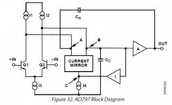
I don't think op amps are so diabolic as you said: I like vacuum tubes, now I'm building a modified Atma Sphere OTL , but I don't disregard what technology today offers. Op amps are very useful in many applications and one of these is just regulated power supply. I'm not the one, not the first and surely not the last who use op amps in this kind of applications, Walt Jung "docet". All his regulator are op amp based, and certainly he's not the last coming in this applications.
Also if you take a look at AD797 datasheet you see that it shows impressive electrical characteristics: GBP 110 MhZ, SR 20 V/us, CMRR 130 dB, PSRR 130 dB, Input Voltage Noise 0.9 nV/sqrt(Hz), THD -120 dB. If you see block diagram of AD797, attached at this post, you can deduce it works just as you ask, so I think it will work as just as well as discrete replication.
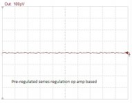
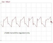
I'm not sure that a simple monolithic IC regulator do the same work of a pre-regulation followed by a series voltage regulator rejecting ripple and noise.
I attach two simple simulations of both configurations: as you can see there are at least 120 dB of difference between the two options. Just why I chose to adopt this configuration, followed by a feed forward shunt regulation that improve noise rejection and transient response.
In a future post I'd like to discuss about how fast should be the circuit response to the transient pulse. For now I can say that I prefer series regulation rather than shunt regulation, just because tipically it's slower than shunt. That's why I chose a feed forward shunt at the end of the regulator, only to act a limited noise cancellation, a little more than 1 mV. Most of the work is done by the series regulator.
Andrea
Attachments
No..................... Walt Jung ...........All his regulator are op amp based.................
Many of his example regulators, in his various papers, use discrete active devices and some do not use any IC, they are solely dependent on discrete devices for their exemplary performance.
No.
Many of his example regulators, in his various papers, use discrete active devices and some do not use any IC, they are solely dependent on discrete devices for their exemplary performance.
Andrew,
I have not read all Jung's documentation, but his most famous regulator, the 2000's Jung Super Regulator, use an AD825 as circuit feedback control. Also his previous version use an AD797.
In his article "Low noise power for analog circuits" he use an OPA165 and AD780/AD589 as voltage reference.
Do you really think is not possible to build an high performance regulated power supply with op amps and discrete devices?
Do you think you get better performance using a couple of 2SK170 plus a couple of BC550, a mosfet and a zener or an LED as voltage reference?
Don't forget, for example, AD780 works as a zener, as a super zener, with lower drift and lower noise than the zener.
Andrea
I'm going to write some "Cardinal Rules" for regulators:
1) Regulate the clock Vcc/regulator separately from analog circuitry regulation.
2) Load the regulator for as much current as the pass transistor can handle (heat sinked of course.) If you have to, add a ballast resistor to accomplish this.
3) Don't skimp on trace width.
4) where you think you can use a 1/4 watt resistor use a 1/2 watt resistor.
I would take a look at the layout which Jan did for Jung's regulator and go from there.
Add another 2 rules:
5) Use a fast error amplifier.
6) Use high hfe and/or gm pass devices (this last one is right from Jung's "Don't Shun the Shunt Regulator").
- Home
- Amplifiers
- Power Supplies
- The Well Regulated Power Supply