hello,everyone! the circuit diagram is to achieve the following functions
1 : When the switches(s1,s2,s3) are off, output A is 45v,output B is -45v
2 : when you turn on the s1,the q1 and q2 are off,so the output A is not 45v,and output B is not -45v
3 : when you turn on the s2 (s1,s3 is off) , q5 is on ,so output A and output B are short circuits
4 : when you turn on the s3 (s1,s2 is off) output A is -45v,and output B is 45v
the logic circuit is no problem On the whole,but it should be improved because of high import input voltage.i am not good at modern circuit ,and i do not know how to add some protection circuits
thank you for helping me ,thanks!
An externally hosted image should be here but it was not working when we last tested it.
There are many problems here.
Assuming GND is a midpoint between - and + 45 volts (that is to say GND is your zero point) then Q1 and Q2 can not output more than around 4.3 volts on their emitters because the bias voltage (Vcc) is only 5 volts. Outputs A and B can only ever be even less than this.
Not sure what you are trying to achieve here but this will never work I'm afraid.
Q5 ? would be destroyed (and probably all before it) as it always shorts the switched rails. Any voltage differential of more than 0.7 volts across B and E will do this.
You need the logic to be foolproof for a start if accidents are to be avoided. That means arranging so that there can never be any overlap or crossconduction. For example Q5 must never be able to be turned on if Q3 and 4 are on. Not even for a few microseconds. That applies to all transistors that "short" rails.
Q1 would be better as a PNP and the base pulled low to activate and Q2 an NPN with the base pulled high. That would give minimal voltage losses using transistors as switches. That applies to all the series rail switches. You would need suitable level translation between the logic and all these transistors.
To do it right is quite a major design exercise.
i am a freshman,i find it hard to do this .If time allows,would you help to draw it ? i really need an experienced person to do it
what i want to do is to finish the following functions, 1:, disconnect 2 :short circuit 3:switch drop
what i want to do is to finish the following functions, 1:, disconnect 2 :short circuit 3:switch drop
Last edited:
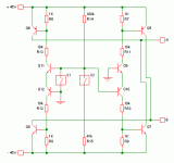
Here is a start, with just S1 and S3.
When both switches are open, R14 pulls the voltages on the bases of Q11 and Q10 up. Q11 is switched on so current flows through Q11 and Q12 to switch on Q6 and Q8. Q10 is switched off, so no current flows through Q10, Q9, Q5 or Q7.
When S3 is closed, R15 pulls the voltages on the bases of Q11 and Q10 down. Q10 is switched on so current flows through Q9 and Q10 to switch on Q5 and Q7. Q11 is switched off, so no current flows through Q11, Q12, Q6 or Q8.
When S1 is closed, the bases of Q10 and Q11 are both grounded, so both are switched off and no current flows through any of the transistors.
Switch 2 may be difficult. If you can use a 2-pole 2-way switch, then it is very easy; you can just connect the switch so A and B are either connected to the power supply or to ground. If you have to use a single-pole single-throw switch then it is more difficult. Do A and B only have to be shorted to each other, or must they both be shorted to ground? Are you allowed to use a relay, or only transistors?
Attachments
Here is a start, with just S1 and S3.
When both switches are open, R14 pulls the voltages on the bases of Q11 and Q10 up. Q11 is switched on so current flows through Q11 and Q12 to switch on Q6 and Q8. Q10 is switched off, so no current flows through Q10, Q9, Q5 or Q7.
When S3 is closed, R15 pulls the voltages on the bases of Q11 and Q10 down. Q10 is switched on so current flows through Q9 and Q10 to switch on Q5 and Q7. Q11 is switched off, so no current flows through Q11, Q12, Q6 or Q8.
When S1 is closed, the bases of Q10 and Q11 are both grounded, so both are switched off and no current flows through any of the transistors.
Switch 2 may be difficult. If you can use a 2-pole 2-way switch, then it is very easy; you can just connect the switch so A and B are either connected to the power supply or to ground. If you have to use a single-pole single-throw switch then it is more difficult. Do A and B only have to be shorted to each other, or must they both be shorted to ground? Are you allowed to use a relay, or only transistors?
good,you really make a penetrating analysis ,, i admire you very much.A and B only have to be shorted to each other, no must they both be shorted to ground. of course ,a relay is allowed ,but i I never used,if you can solve the swithch 2 problem by transistors,i can understand easily.
would you help me solve this problem ,thank you very much . good friends ! welcome to china!
,
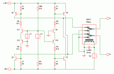
Switch 2 functionality would be very difficult with transistors. With a relay, it is very easy. Switch 2 just has to connect 45V to the coil of the relay. Something like this would be good: PCB Relay DPDT 8A 48Vdc
Switch 2 functionality would be very difficult with transistors. With a relay, it is very easy. Switch 2 just has to connect 45V to the coil of the relay. Something like this would be good: PCB Relay DPDT 8A 48Vdc
can you draw a picture ? i a little do not know what you mean
if use transistors? can we add a logic inverter as i used in the original picture to make the q5 on ?
Oh, OK. sigh...can you draw a picture ?
I don't know how to do it with transistors.
This is with a relay. Why don't you Google "relay"? It is easy to understand.
Attachments
Oh, OK. sigh...
I don't know how to do it with transistors.
This is with a relay. Why don't you Google "relay"? It is easy to understand.
thank you for concerning about this topic ,i have a lot of thing to do at this moment, i am away from campus to to take an examination. and i can not concentrate on my design ,several days later,i will have the time .
thank you very much . my name is lin xiao xin. i am a man of making with friends.have you used the qq Chat Tool ,or you just used the msn ?
actually,my tutor ask me to do it with transistors,because the transistors swith frequency should be 1 mhz. it is to say that the switch time should be controlled at 1 us. and the relay can not reach it.
I will be very interested to see how you do that. I do not know how.actually,my tutor ask me to do it with transistors....
Someone is going to press the button a million times per second?....because the transistors swith frequency should be 1 mhz. it is to say that the switch time should be controlled at 1 us.
- Status
- This old topic is closed. If you want to reopen this topic, contact a moderator using the "Report Post" button.
- Home
- Amplifiers
- Power Supplies
- protection circuits (swith circuit)

