Filters rated for say 4 amps will handle the actual 12 amps or so a linear power supply peaks at. That is because the average current stays within ratings and there is some concern about selling things that do not catching fire. The issue is that the inductors may saturate at some point during the current draw and reduce the amount of filtering.
Power supplies that use an inductor for filtering will have smoother average current draw and not stress the filter or even the power line resistance as much as a straight to the capacitor filter.
Inductor filtered power supplies are most often used in vacuum tube equipment. Vacuum tube equipment is much less affected by EMI noise sources than semiconductor equipment. (Still some effect.)
Increasing the resistance by adding inductors can be estimated by allowing .2 ohms for the AC delivered through a power cord into the filter. Use the expected peak power to determine the average peak current draw. Multiply this by 3 for a typical peak current. Then that current time the added DC resistance will give you your primary side voltage loss at peak load. If it is more than 10%, some folks may hear that. Many will claim to.
Wow...I didn't expect a multi page debate.
To add more fuel to the fire, here is an attenuation loss graph of Schurter DD12, 4A version
. . . . . 0.1/100Ω differential mode
........... 100/0.1Ω differential mode
- - - - differential mode
_____ common mode
Diagram:
L 2 x 1.5 mH
Cx 100nF
Cy 2.2 nF
R 1M
To add more fuel to the fire, here is an attenuation loss graph of Schurter DD12, 4A version
An externally hosted image should be here but it was not working when we last tested it.
. . . . . 0.1/100Ω differential mode
........... 100/0.1Ω differential mode
- - - - differential mode
_____ common mode
Diagram:
An externally hosted image should be here but it was not working when we last tested it.
L 2 x 1.5 mH
Cx 100nF
Cy 2.2 nF
R 1M
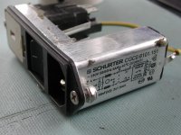
Great...I am planning to use a Schurter power entry module with a switch, fuses and a filter - all in one package makes everything simpler and cleaner
Exactly what I've been using, these were pulled from prototype breast biopsy devices, now recycled into my tube amps.
Attachments
My opinion:
If you hear a difference between filtered and unfiltered comes because you know when the filter was there or not.
After rectifying there is a DC voltage on your caps, and there is no difference there with or without filter.
Since you amplifiers works on DC voltages, I think the sound difference is between your ears!
Yes AC line filter does help, at least for the setup of my home equipment.
This is the REAL EXPERIENCE I got just from yesterday and I want to share
my experiences with all people who enjoy high quality music.
I've a AK4396 Dac with Singled ended FET line buffer driving my AKG K501
for listening music from my home PC. It works fantastically and the sound
quality is crystal clear, sound stage are miracle, imo.
Yesterday , I rearrange the placement of my equipment to make it more tidy.
After the tidy up work,I found the sound output from my headphone become dull. The sound is still good, but the stereo image is lost. It's still two channel, you can hear sounds come out from left and right side differently but the feeling of stereo image is lost, just like hearing a cheap earphone connect to low quality computer audio output.
I at first think that's because of my own body condition (may be two tired),
but after one day, I am sure that there is something wrong with my equipment. I then check in detail what has been changed and find out that
the DAC/headphone amp is now connected to a different A/C power band.
I then examined what is the difference between the original and new power
band. The difference is that the original power band has a A/C power line filter
(just a very cheap , some 3 dollar i think) I added 3 year ago.
I remembered that I added this filter just for fun and never expect there will have any difference. After I re-plug my DAC to the original power band,
everything goes to normal. The stereo image come back.
I am not sure it is the cause of A/C line filter that make the difference.
But for sure, the condition of A/C power source does has great influence on the sound quality. So my recommendation is that everybody should try adding
A/C line filter if it is not included in your equipment, especially if it shares
the same power source with your computer.
the pics in post1 and post24 show filters designed to be fitted through a hole in the enclosure.
Both have a recess in the plastic moulding to allow a neat hole for back of panel fitting.
Most Builders will mount these filters on the back of panel since clearly that plastic moulding is designed for that purpose.
BUT !
separating the filter metal case from the hole through which it should pass allows interference to pass through that hole.
And worse the interference filter takes the cable interference to the enclosing metal can with no where for that interference to go, except via the PE connection via a long wire.
For best RF attenuation the metal can should be in contact with the enclosure hole all around the perimeter. No gaps equals no leaks of GHz interference through the hole.
This requires the filter to be inserted through the hole from the outside and then bolted in position with electrical contact from can to chassis to conduct interference direct to enclosure without having to pass along the inductive impedance of the long PE wire.
We are not done yet.
The can to enclosure connection requires good electrical contact to be effective in taking interference to the enclosure.
That requires the electrical contact to be maintained over years of operation. The contact needs a non corroding electrical gasket of protection using some air excluding jointing grease/vaseline/or All Aluminium, or All Steel connections clamped airtight.
Is the can steel or aluminium?
If the can to enclosure contact were to corrode all around, then we are left with capacitive conduction of interference. All is not lost. The frequencies are often so high that quite small capacitances will still allow the filters to work. The area around the hole and corrosion filled gap give more than a few pF, possibly hundreds of pF.
Last edited:
The filters shown in pics 6 & 7 requires the cans to be bolted to the enclosure and preferably near where the cable enters the enclosure.
The cable between the enclosure entry hole and the can terminals requires to be screened and both ends of the screen need to be connected by low impedance methods to the enclosure. This means very short pigtails, or much better: a metal clamp to pull the exposed screen into contact with the enclosure wall.
The cable between the enclosure entry hole and the can terminals requires to be screened and both ends of the screen need to be connected by low impedance methods to the enclosure. This means very short pigtails, or much better: a metal clamp to pull the exposed screen into contact with the enclosure wall.
My experience of IEC panel insert modules and other mains filter modules correctly fitted/wired is that they do indeed reduce mains borne noise (as advertised) and a bunch of consequent downstream maskings caused by effects on circuitry of this longitudinal noise, BUT they can also cause a dullness/information loss, a low level constant distortion and a 'hardness' that I attribute to the inclusion of ferrite.
IIRC member Dvv recognises this and recommends powdered iron inductors as preferable.
According to a Youtube video showing the internals of a panel insert integrated IEC socket/fuse/filter assy, the filter input stage A-N cap (post fuse) is designed to fail short, and the A-E and N-E caps are designed to fail open.
What is the construction and chemistry of these X rated and Y rated caps ?.
Dan.
Last edited:
An X cap is not designed to fail short. It is designed to fail open, but this is less guaranteed than for a Y cap. The idea is that an X cap won't burn your house down, but a Y cap won't electrocute you.
There are several technologies used for X and Y caps. Most use plastic film, but some are ceramic.
There are several technologies used for X and Y caps. Most use plastic film, but some are ceramic.
You could try an experiment. Put one of those in its own metal chassis, with IEC inlet and IEC outlet. Then (a) listen to your audio system with the filter inserted in series between the AC mains and the Device-Under-Test; (b) remove the filter and listen to your audio system again with NO filter inserted in series between the AC mains and the Device-Under-Test.
Is there any difference at all? If so, which of the two sonic presentations do you prefer?
Is there any difference at all? If so, which of the two sonic presentations do you prefer?
- Status
- This old topic is closed. If you want to reopen this topic, contact a moderator using the "Report Post" button.
- Home
- Amplifiers
- Power Supplies
- AC Line Filter