Hello,
So, I've been trying to bias the left and right sides of my 805 SET tube amp. I can't quite get it right. One side is showing about a 10% difference which I can trace back to the power supply and/or/hoperfully the filtering.
The 390V tap is putting out aprox 360-370V and that makes aprox 860-870V on the B+ which ought to be 950V It's about 10% shy.
What is the likely cause?
Judging by the schematic Is there anything I could do?
Am I being too fussy???
Hello,
So, I've been trying to bias the left and right sides of my 805 SET tube amp. I can't quite get it right. One side is showing about a 10% difference which I can trace back to the power supply and/or/hoperfully the filtering.
The 390V tap is putting out aprox 360-370V and that makes aprox 860-870V on the B+ which ought to be 950V It's about 10% shy.
What is the likely cause?
Judging by the schematic Is there anything I could do?
Am I being too fussy???
yes, i believe you are being fussy....
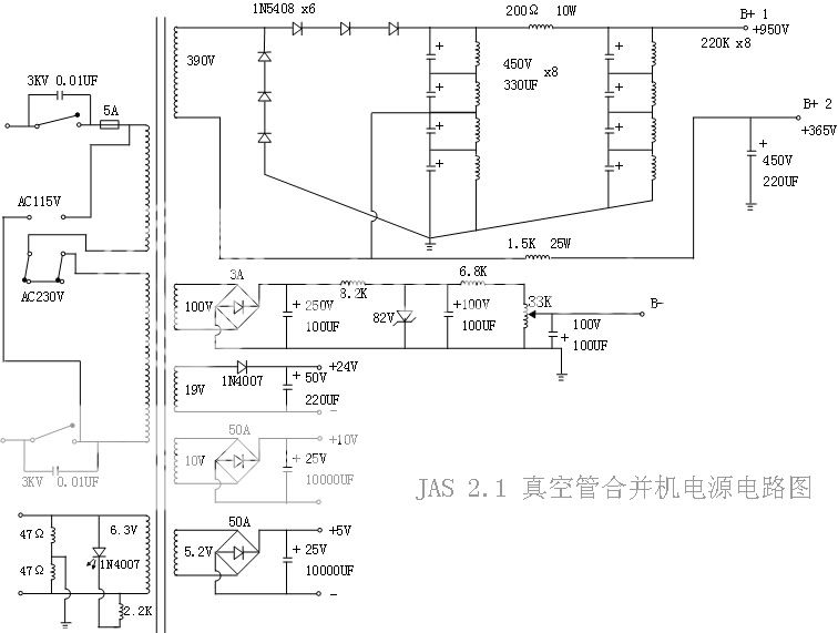
with a 390Vac transformer secondary, your unloaded voltage should be right around 1092 volts....now as you load your power supply, this voltage drops owing to the secondary dc resistance of your 390volt winding and the 200 ohm resistor in your psu.....
the thing you need to do is set the grid bias voltage to maximum negative...then when filaments are fully aglow, you can then set you bias voltage to get your plate currents to desired value.... you will notice that B+ starts going down with plate current....
if you can post the schematics of your 805, we can look further....
your B+ going lower than desired means that the traffo that you got is a tad lower than what you need, your primary voltage can also be lower so that secondary voltages are likewise lower.........with voltage doublers, what i do is to put several taps on the traffo secondary so i can adjust voltages.....
with tubes, voltage drops on the psu to 100 volts is nothing unusual.....
Last edited:
42 volt drop across the resistor, on both sides! However the one on the good side is on 998V and the low side is 937V
B+ 2 is also running a little low. When I set the grid bias even on both sides the voltage on the plates is lower on the low side by 25-35V or so.
imho....nothing to lose sleep about....

are those plate voltages? the important thing is to get your plate current right....
they must be plate voltages....one having 937volts is drawing more current than the one with 998....
i notice there is something wrong with your grid bias circuit....as drawn....
What's that?
Have you checked correct function of your diodes? Had the same problem once, turned out to diodes were out of spec....
I think I'll start by taking it apart and checking, I was thinking this already, maybe it's letting some ac by as the low side tranny seems to have very slightly more mechanical vibration. (Is that how this works???)
If safe to do so, can you run PSU on its own with nothing attached to see if the doubler has a problem.
CHECK that diodes and caps are rated sufficiently high enough for NO LOAD operation.
Sure no sweat, if I'm going to be taking it apart anyway, but How do I know if it's safe??? (obvoiusly not to safe for me at 1000V if that's what you mean, but I'm able, the question is it safe for the amp?) Caps are all 400V 1000uf and the diodes are IN5408.
Last edited:
i notice there is something wrong with your grid bias circuit....as drawn....
Diode!
Diodes check out,
What about that 200ohm value resistor, if I change that will B+ 2 voltage also change with B+ 1?
Could I balance the power output that way?
I know the resistor is in parallel with the B+ 2 so theoretically shouldn't, but electricity doesn't always seem to behave but maybe because I don't fully understand it yet?
Last edited:
B+1 and B+2 are inextricably intertwined....it comes from the same secondary winding.....
yes, the 82v zener was drawn backwards....the 805 is a zero grid bias tube.....positive voltage is required to make it draw plate current.....you must be using IT to drive that grid as it requires power to push those grids around.........
if there is something wrong with your diodes, 1n5408's you wouldn't even have dc voltages....
3 x 1n5408 in series gives it a 2.4kv piv rating, 3 x 450v series ecaps gives it a 1350volts working volts dc rating.....just make sure the those resistor shunts accross the caps are rated for 3watts, and 390k ohms or thereabouts.....
Quote:
Originally Posted by Tony
i notice there is something wrong with your grid bias circuit....as drawn....
Diode!
yes, the 82v zener was drawn backwards....the 805 is a zero grid bias tube.....positive voltage is required to make it draw plate current.....you must be using IT to drive that grid as it requires power to push those grids around.........
CHECK that diodes and caps are rated sufficiently high enough for NO LOAD operation.
if there is something wrong with your diodes, 1n5408's you wouldn't even have dc voltages....
3 x 1n5408 in series gives it a 2.4kv piv rating, 3 x 450v series ecaps gives it a 1350volts working volts dc rating.....just make sure the those resistor shunts accross the caps are rated for 3watts, and 390k ohms or thereabouts.....
.....just make sure the those resistor shunts accross the caps are rated for 3watts, and 390k ohms or thereabouts.....
found some bad load resistors drifting too low on the side I thought was good, ha ha, probably right side of amp is putting out too high a voltage vs left side being lower... I'll be placing an order on parts fairly soon, I'll let you know If that doesn't work.
I'm just going to replace all of them, would you recomend beefing them up from 220K to 390K? Are load and shunt resistors are the same?
How much would that effect output?
and
Would you recomend metal oxide or film for load resistors.
they all should be the same value, i use between 220k to 470k and at times even 1meg, what is important is that they all measure the same so that voltage is equally divided among those capacitors......
metal oxide will be better so that they don't drift in value over time.....these are also bleeders....to discharge those caps on power down....
metal oxide will be better so that they don't drift in value over time.....these are also bleeders....to discharge those caps on power down....
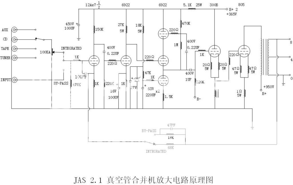
The 12AX7 is inside the amplifier's feedback so you might want to leave it unless you are planning some analysis and redesign before proceeding. Interestingly in bypass mode the feedback margin is about 14dB higher than in integrated mode, the amplifier probably sounds quite different in the two modes? (stable?)
The bias supply is negative, both the electrolytics and bridge rectifier are probably shown incorrectly. Since the plate supplies are not regulated regulating the bias supply is fairly poor design practice. You might redesign so that the bias tracks changes in line voltage as the plate supply does, this will result in somewhat less shift in operating point with changing line voltage. (Not perfect though)
I would expect that at 1kV an 805 would not need to driven too far into grid current to get reasonable output power.
yes, the 805 needs positive grid bias in order to draw current....you can monitor the voltage accross the 1ohm resistor at 805 cathode circuit to know your bias point.....the 805 can dissipate 125 watts in its plate, so assuming you wnt to run it at 100watts plate, then at 900volts plate voltage, plate current is 110mA, so that you should be able to measure 110mV across that 1 ohm resistor....
take note of the dc resistance of the cathode choke at the cathode of the 300b.... ohms law will tell you the correct voltage drop accross that choke so that the 300b is biased at 60mA....by adjusting the negative grid bias of the 300b...
the psu biasing is drawn wrongly just as i thought....the 300B needs negative grid bias....
Last edited:
42 volt drop across the resistor, on both sides! However the one on the good side is on 998V and the low side is 937V
B+ 2 is also running a little low. When I set the grid bias even on both sides the voltage on the plates is lower on the low side by 25-35V or so.
Hi,
Set the bias for equal current and then measure your voltages. If the B+ then checks out OK but the bias voltages differ alot for equal current you should try to get another 805 for the bad side.
BR,
Anders
- Status
- This old topic is closed. If you want to reopen this topic, contact a moderator using the "Report Post" button.
- Home
- Amplifiers
- Power Supplies
- Am I loosing power somewhere?