Hi All
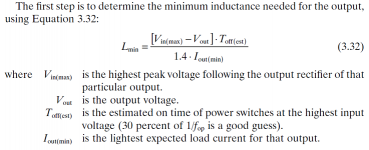
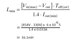
I am presently building a 12V to 330V converter and I have been using a book titled Power Supply Cookbook by Marty Brown as a guide. There is a formula that appears within for calculating the output choke value that I am having a tough time grasping as it seems the result is rather big for such a small smps.
The smps operates in push-pull config at 50kHz and is rated for 120mA max. Vin(min) = 11V
Vin(max) = 15V
Can someone please have a look at my calc. and advise if I misunderstood what was required?
Thank you
Ashraf
Attachments
The inductor at the output only smoots the voltage, and operates as a low pass filter with the out cap. Assuming a delta I, the choke is easy to calculate. Normally it is assumed as a 10% of I load. I also have this book, but it is a bit confusious the math he use. Read any inductor calculation for buck converter type, in fact the inductor operates in the same way as it.
Osvaldo, are you saying that calculating chokes for buck converters are exactly the same as calculating an output choke for a forward converter?
Yes!!!
http://www.ti.com/lit/ml/slup127/slup127.pdf
I hope this be usefully.
Anybody??
The formula is dimensionally correct.
The only point open to debate is the 1.4 factor, it represents the level of ripple you tolerate for the current in the choke, but even if you choose a different trade off, the value will remain in the same range.
It is a normal value for a high voltage converter: the inductance value increase as the voltage squared.
Thanks for your responses.
Osvaldo, I read the TI note and I can't seem to find where it explains how the inductance of the choke was calculated. The inductance value of the choke was provided all that the note said was what type of core, winding etc.
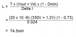
Elvee, I came across a somewhat differennt formula for calulating the choke from Col. T. McLyman and when I did the calculation I come up with a value of 74.5mH. Now I am more confused as to which value is the correct one.
Jay, I don't understand your question. Please will you rephrase.
Osvaldo, I read the TI note and I can't seem to find where it explains how the inductance of the choke was calculated. The inductance value of the choke was provided all that the note said was what type of core, winding etc.
Elvee, I came across a somewhat differennt formula for calulating the choke from Col. T. McLyman and when I did the calculation I come up with a value of 74.5mH. Now I am more confused as to which value is the correct one.
Jay, I don't understand your question. Please will you rephrase.
Attachments
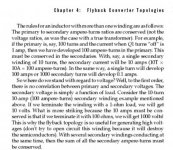
What the boy below said about the high value of inductances needed for high voltages outputs is very true. Why don´t try any topology that don´t need choke, like flyback, the best suitable for high voltage output, or any topology that pushes the inductor to the primary side. Google with "current feed push pull" by example. In this case, the inductor will have more rasonable values. Also, I suggest
http://bhagirathi.iitr.ac.in/dspace/bitstream/123456789/962/1/DCC003.pdf
It is well explained, there is an example to demonstrate calculus, and I will try this topology for a 12 to +-14V converter.
Good luck.
http://bhagirathi.iitr.ac.in/dspace/bitstream/123456789/962/1/DCC003.pdf
It is well explained, there is an example to demonstrate calculus, and I will try this topology for a 12 to +-14V converter.
Good luck.
Last edited:
Osvaldo, the Flyback converter at first glance seems like a good alternative however it seems that there should be a load attached to it at all times. The application note I read states that if you run the converter without a load attached you will end up destroying the switching elements. 
The current fed push-pull converter seems like a much better alternative albeit you can no longer use the SG3525. I have requested samples of UC3827-1 from TI. Can't wait to test these out.
Thanks for info.
The current fed push-pull converter seems like a much better alternative albeit you can no longer use the SG3525. I have requested samples of UC3827-1 from TI. Can't wait to test these out.
Thanks for info.
Osvaldo, the Flyback converter at first glance seems like a good alternative however it seems that there should be a load attached to it at all times. The application note I read states that if you run the converter without a load attached you will end up destroying the switching elements.
The current fed push-pull converter seems like a much better alternative albeit you can no longer use the SG3525. I have requested samples of UC3827-1 from TI. Can't wait to test these out.
Thanks for info.
1) I don´t know who told you or where do yo read that a FB converter is destroyed without load. It is totally false. The vast majority of the PC monitors (tube or flat), notebook SMPS´s, TV sets, and much more circuits has FB topology with no destroying nothing. Normally, the FB converter enters in a special mode of working known as "Hiccup" or "cycling" mode in which the SMPS entirely starts, replenish the output caps, and stops as quickly it goes to the output voltage and then, in case of very soft or no load, the cap continues charged, and then the controller stops the SMPS, running at intermitent mode 3,4, 5 clock pulses and stops, in some case, for very seconds. No SMPS I know are destroyed in such circumstances. At least, you can place a led and a resistor sinking about 10mA and all OK. Read some special info about the ST´s Viper100 who is especially designed for no load, and perhaps be more suitable a boundary conduction mode flyback quasi resonant like the ST´s L6565 PWM controller (I didn´t try them yet).
2) Also false. There is a option to the UC/SG3525 family (UC/SG3527) that has its outputs inverted, easy to drive MOSFET´s, or add a CMOS inverter at the output of the controller, and it will give deltas in the range or 50 to 100%. Also the simplest UC3524 using the collector outputs and placing a MOSFET driver like MIC4420 (non inverting) or MIC4429 (Inverting) are alternatives for the current fed. Keep in mind in those cases, the the internal operational amplifier will work backwards: the NI input will be the the inverting, and viceversa.
Salu2 para to2.
Last edited:
I actually read about the FB open circuit in Pressman's book as I have no experience with FB topologies
Archie: in the text it is very clear: when you have a high voltage across any winding, if left unloaded, the voltage increases, and then may arc between the turns of the coil, it isn´t a disadvantage of the FB topology itself. I made so many years ago a FB topology that generates a 5KV output starting from 24V to drive a CRT monochrome via a multiplier of caps and diodes. To this date, it hasn´t failed. The high voltages stress is inherently of ANY kind of transformer that may support it. In example: line transformers in PC monitors, TV sets, neon announcements, static/antistatic sprayers, car ignition, etc. Remark the piece of text where he told "very useful to generate high voltages..." because it doesn´t need output inductors.
Again, this kind of failure isn´t a property of FB SMPS topology.

Good luck.
Last edited:
Again, it isnt a property of FB SMPS topology.
It is: without regulation, limitation or a loss mechanism, the open circuit voltage can rise indefinitely.
By contrast, a forward converter might have a no-load voltage somewhat higher than when loaded, but the ultimate voltage has a definite upper bound.
Dear Archie and Elvie: even the very very small load imposed by a voltage divider to make secondary voltage sense via a photocoupler and a TL431 (It tooks 4 or 5 ma for proper operations) normally is sufficient. A converter topolgy that needs a choke output are never used to generate high voltages.
And, finally, you are talking about 330V. You need about 1000V/millimeter to make an arc in free dry air, and in the coil, it will take several turns to give such a voltage, and then the voltage between adjacent turns is low.
Here in Argentina, we use three phase voltage of about 380VAC, when rectified it is about 540VDC. Lots of frequency inverters for AC motor (ABB, AB, Siemens, etc) uses this high voltage to energize a flyback converter down to 5V, 12 and or 24V. Sincerely I never saw any failure IF THE TRANSFORMER IS PROPERLY DESIGNED.
A properly designed and regulated flyback can work perfectly well and reliably, but anyway the transformer acts as a choke, stores energy, and has to be designed to the same standards as the choke of a forward converter.Osvaldo, It isn't as clear cut as you say. I trust that you have lots of fate in FB designs. I just need to be certain that FB will suit my application as there may not be a load attached at all times and the load can vary as well.
Except of course that because of the lower utilization factor due to asymetric operation, it needs to have twice the energy capacity storage, and therefore approximately twice the volume everything else being equal.
But a symetric converter requires at least two active elements....
Elvee: you are right,. But remember that energy storage is gobernated via the main switcher by the PWM controller, and a feedback loop, so energy entered into the "mutually coupled inductor" (NOT TRANSFORMER) equals energy removed from secondary, so it will not explode by accumulated energy not delivered to secondaries (And a tertiary if there is a coil winding for auto maintain the primary side as in PC monitors or notebook SMPS´s).
Again, normally the most of the SMPS´s I see, repaired and designed, enters a sort of low frequency start and stop when no load (Hiccup mode or pulse skiping or so) and maintaining mean output value although with higher low-frequency ripple. I never saw a uncontrolled SMPS generating "megavolts" at it output under no load conditions.
Again, normally the most of the SMPS´s I see, repaired and designed, enters a sort of low frequency start and stop when no load (Hiccup mode or pulse skiping or so) and maintaining mean output value although with higher low-frequency ripple. I never saw a uncontrolled SMPS generating "megavolts" at it output under no load conditions.
- Status
- This old topic is closed. If you want to reopen this topic, contact a moderator using the "Report Post" button.
- Home
- Amplifiers
- Power Supplies
- Choke formula - Marty Brown