I saw the thread on this here.
But I was wondering if there couldn't be something even simpler, with less parts, and perhaps more reliable. Also It should work, not by voltage per se but by detecting a voltage difference, or rather none, between sides of the push-pull output tubes.
That is, a simple circuit that measures if there is a voltage difference (indicating a current difference, because of equal resistances in the cathode resistors), and sets a red light if its either negative or positive, that you could watch while adjusting the balance (not of the drivers, but of the output currents through each half of the output tranny).
Here's that ST-70 circuit for starting off:
Gingertube's explanation is fine:
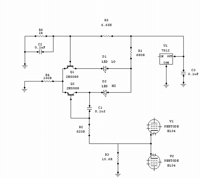
But I want something simpler, along the lines of these examples:Think of Q1 and Q2 forming a comparator.
When Q1's base voltage is higher than Q2's base voltage then Q1 hogs all the current and holds Q2 off, LED1 (LO) will be on. When the reverse is true Q2 hogs all the current holding Q1 off , LED 2 (HI) will be on.
R5 and R6 set the reference voltage to Q1 base
Vref = 12 ( R6 / R5+R6) = 1.59 Volts
R3 is the current sense resistor.
At 100mA through R3 you get 1.56 Volts which is less than 1.59 and LED 1 (LO) will be ON.
At 104mA through R3 you get 1.62 Volts which is more than 1.59 and LED2 (HI) will be ON.
To work at a different current you can either:
Change the reference voltage at Q1 base by changing R5 (or R6)
OR
Simply change R3 so that the current you want will give 1.59 Volts.
That is new R3 = 1.59/ Current required.
Cheers,
Ian
An externally hosted image should be here but it was not working when we last tested it.
An externally hosted image should be here but it was not working when we last tested it.
The idea is that there would also be a BIAS supply, or adjustment resistor in the case of a self-bias circuit,
with a trim-pot wired up with suitable safety bypass resistors in case of an open-circuit pot (that is a separate task, but doable).
You would simply look at two or three LEDs, or maybe a two-in-one, which showed red when there was some imbalance say more than a 1/10 of a volt or something to indicate more than say 10 mA of current difference per tube-pair.
So, it would go RED for too much current left-side, GREEN for a close balance, and RED again for too much current on the other side.
For now, I would adjust the BIAS / balance while the circuit idles without a signal.
Later, I'd like to use the same basic circuit for an auto-adjustment (something like a voltage regulator) to keep the current through the cathode resistor of each tube constant.
I know you're saying, "But the current ISN'T constant!" Its a push-pull for crying out loud!"
But in my circuits, I'm aiming for a class-A constant current output stage. Also, I'd like the circuit to perhaps either self-adjust slowly (lower than 20 Hz perhaps) or take extended samples of the instantaneous current, to then compensate by attempting a slow tilt of the current back to center on each side.
But the main point for now, is there ought to be an elegant and VERY simple circuit with only a few resistors and LEDs (maybe a zener or two) that can do this basic indicating job. (detect a voltage to ground difference between two points).
Last edited:
Lets take the 2nd Last picture:
Now compare that to the 2nd example (which gives a value for the measure-resistor):
Somehow we want to combine both ideas (the best from each).
Here is our basic Cathode-biased output stage:
For this to work, the separate legs of the Push-Pull stage have to operate independently. So any connection between the two cathodes has to be high resistance/impedance.
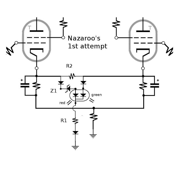
R2 will be the sensing resistor, used to catch any difference in voltage (to ground) between the cathodes. This will be a good indicator of current difference, because the resistances to ground for each side should be the same. Same voltage then means same current.
The original circuit used a fuse. When blown, power remained on the red pole of the dual color LED, giving RED. Presumably with the load on, the Zener dropped the voltage to the Red LED enough to either turn it off or leave it dim.
In our circuit, R2 must be high (to isolate the two sides), Z1 must be adjusted for a similar effect/ purpose as the original circuit,and R1 must be chosen to properly bias both LEDs for the given BIAS voltage.
The BIAS / Balance would presumably be set without a signal, and when the Red LED shuts off or dims and the Green LED lights up, we would suppose the current is balanced.
(1) Since the circuit is cathode-biased, all hell breaks loose when the music is playing, and the LEDS won't mean anything then.
(2) One obvious problem is that both LEDs might be on at the same time, making the reading confusing and also perhaps overheating the dual LED package.
(3) Also, the circuit seems cumbersome and already has a lot of components. To make a full version (indicating both left and right BIAS offsets, you'd have to again double the circuit (one for each side) and double the adjust-pots (not shown) to independantly both lower and raise current/bias on either leg.
(4) I would also like to see the LEDs powered by independent circuits instead of drawing on the cathode current, which may affect the sound, especially if they are shutting on and off.
Thats why we want to look at the other circuit, which has some advantages:
It uses an additional transistor, which presumably detects more accurately a voltage DIFFERENCE between the two legs, and perhaps can be modified to minimize noise or interference with the amplifier.
Now compare that to the 2nd example (which gives a value for the measure-resistor):
Somehow we want to combine both ideas (the best from each).
Here is our basic Cathode-biased output stage:
For this to work, the separate legs of the Push-Pull stage have to operate independently. So any connection between the two cathodes has to be high resistance/impedance.
R2 will be the sensing resistor, used to catch any difference in voltage (to ground) between the cathodes. This will be a good indicator of current difference, because the resistances to ground for each side should be the same. Same voltage then means same current.
The original circuit used a fuse. When blown, power remained on the red pole of the dual color LED, giving RED. Presumably with the load on, the Zener dropped the voltage to the Red LED enough to either turn it off or leave it dim.
In our circuit, R2 must be high (to isolate the two sides), Z1 must be adjusted for a similar effect/ purpose as the original circuit,and R1 must be chosen to properly bias both LEDs for the given BIAS voltage.
The BIAS / Balance would presumably be set without a signal, and when the Red LED shuts off or dims and the Green LED lights up, we would suppose the current is balanced.
(1) Since the circuit is cathode-biased, all hell breaks loose when the music is playing, and the LEDS won't mean anything then.
(2) One obvious problem is that both LEDs might be on at the same time, making the reading confusing and also perhaps overheating the dual LED package.
(3) Also, the circuit seems cumbersome and already has a lot of components. To make a full version (indicating both left and right BIAS offsets, you'd have to again double the circuit (one for each side) and double the adjust-pots (not shown) to independantly both lower and raise current/bias on either leg.
(4) I would also like to see the LEDs powered by independent circuits instead of drawing on the cathode current, which may affect the sound, especially if they are shutting on and off.
Thats why we want to look at the other circuit, which has some advantages:
It uses an additional transistor, which presumably detects more accurately a voltage DIFFERENCE between the two legs, and perhaps can be modified to minimize noise or interference with the amplifier.
Turning to the second reference circuit,
at first it looks more complicated, with the added transistor,
but the overall parts count is low, and the circuit looks simple.
It seems to only detect current in one direction, so we need again to double up:
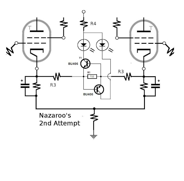
Also, since we still want isolation between the two cathodes (and little current flowing directly across), we have added R3 (split on either side to force the current draw of the diodes to draw equally from either leg).
Some questions remain:
(1) Voltage source to power LEDs is assumed to be from elsewhere, and must be significantly higher than the BIAS reference. We have also added R4 to allow a significantly higher voltage source, so that LEDs operate properly regardless of the actual BIAS voltage chosen. Remember, we only want to detect a DIFFERENCE, not set the overall BIAS with this balance indicator and controls.
(2) The 1 ohm detector-resistor (R1) may have to be adjusted to work with the isolating resistors (R3) properly. We want to limit overall current across while maintaining pretty fine accuracy and sensitivity to imbalance, while still being able to independently select a wide range of BIAS for the pair.
(3) We would prefer to connect to ground rather than a +ve supply, so we don't have to add another power supply with its added cost and complexity. This may require different transistors or layout.
(4) This only turns on LEDs (both RED) when there is an imbalance. We'd like to add a green resistor to indicate the circuit is BALANCED properly, but which will not turn on if the BIAS is wrong or if a tube has failed (short or open).
Still more work to do.
at first it looks more complicated, with the added transistor,
but the overall parts count is low, and the circuit looks simple.
It seems to only detect current in one direction, so we need again to double up:
Also, since we still want isolation between the two cathodes (and little current flowing directly across), we have added R3 (split on either side to force the current draw of the diodes to draw equally from either leg).
Some questions remain:
(1) Voltage source to power LEDs is assumed to be from elsewhere, and must be significantly higher than the BIAS reference. We have also added R4 to allow a significantly higher voltage source, so that LEDs operate properly regardless of the actual BIAS voltage chosen. Remember, we only want to detect a DIFFERENCE, not set the overall BIAS with this balance indicator and controls.
(2) The 1 ohm detector-resistor (R1) may have to be adjusted to work with the isolating resistors (R3) properly. We want to limit overall current across while maintaining pretty fine accuracy and sensitivity to imbalance, while still being able to independently select a wide range of BIAS for the pair.
(3) We would prefer to connect to ground rather than a +ve supply, so we don't have to add another power supply with its added cost and complexity. This may require different transistors or layout.
(4) This only turns on LEDs (both RED) when there is an imbalance. We'd like to add a green resistor to indicate the circuit is BALANCED properly, but which will not turn on if the BIAS is wrong or if a tube has failed (short or open).
Still more work to do.
Solving the power supply problem:
In this next version, we shunt the current from the cathodes through the LEDs to ground.
The power essentially comes from the cathode voltage,
eliminating the need for a power supply.
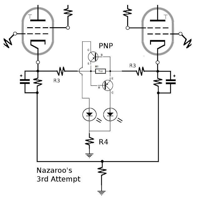
To pull this off, I substituted PNP transistors for the original NPNs.
R4 now should be chosen to handle the expected BIAS voltage,
namely from 40 to 120 volts D.C., keeping the LED currents to a sensible minimum (probably about 10-20 mA).
Presuming that fluctuations during music play would average out, the current drawn by the two LEDs would remain fairly constant on average.
However, the turning on and off of the transistors might introduce unwanted noise. Some kind of bypass/shunt caps, or a high impedance device might prevent any noise from sneaking into the cathode circuit.
Both LEDs here would be red,
indicating the voltages (and currents) were out of balance,
when no music is playing, and the user is adjusting the balance.
If the new circuit introduced excessive noise,
they could be switched off or out of circuit after the balance was set.
Still missing is a green LED indicating that current balance has been achieved,
through the output transformer.
This would light up when there was no cross-current through,
or voltage across the measuring-resistors, but would shut off,
if there was no voltage at all (HV off or Amp off),
or if one tube was shorted out, open, or missing.
Truth Table:
Too much on left : Left Red LED lights. Others off.
Too much on right: Right Red LED lights. Others off.
Perfect balance: Green LED lights. Others off.
No power: All LEDs off.
Fault Condition: (?)
Possible options for a fault condition might be both Red LEDs on (impossible normally),
or a third indicator along with safety features turns on.
In this next version, we shunt the current from the cathodes through the LEDs to ground.
The power essentially comes from the cathode voltage,
eliminating the need for a power supply.
To pull this off, I substituted PNP transistors for the original NPNs.
R4 now should be chosen to handle the expected BIAS voltage,
namely from 40 to 120 volts D.C., keeping the LED currents to a sensible minimum (probably about 10-20 mA).
Presuming that fluctuations during music play would average out, the current drawn by the two LEDs would remain fairly constant on average.
However, the turning on and off of the transistors might introduce unwanted noise. Some kind of bypass/shunt caps, or a high impedance device might prevent any noise from sneaking into the cathode circuit.
Both LEDs here would be red,
indicating the voltages (and currents) were out of balance,
when no music is playing, and the user is adjusting the balance.
If the new circuit introduced excessive noise,
they could be switched off or out of circuit after the balance was set.
Still missing is a green LED indicating that current balance has been achieved,
through the output transformer.
This would light up when there was no cross-current through,
or voltage across the measuring-resistors, but would shut off,
if there was no voltage at all (HV off or Amp off),
or if one tube was shorted out, open, or missing.
Truth Table:
Too much on left : Left Red LED lights. Others off.
Too much on right: Right Red LED lights. Others off.
Perfect balance: Green LED lights. Others off.
No power: All LEDs off.
Fault Condition: (?)
Possible options for a fault condition might be both Red LEDs on (impossible normally),
or a third indicator along with safety features turns on.
Last edited:
Solving the power supply problem for the LEDs:
In this next version, we shunt the current from the cathodes through the LEDs to ground.
The power essentially comes from the cathode voltage,
eliminating the need for a power supply.
To pull this off, I substituted PNP transistors for the original NPNs. ...
(note: I have not built this. Its only a theoretical sketch)
An option is to use a "tri-fferential" with suitable degeneration components.
Here is an example that feeds directly from the HV with a single resistor, and provides ~20mA to 1 of 3 LEDs: the green LED is active when the difference is smaller than +/-300mV, and the corresponding red LED lights when either threshold is exceeded.
Simple, inexpensive and flexible.
Note:
In the sim, the ground is placed on the right output, that's simply to be able to display the difference voltage directly (gray trace).
Attachments
An option is to use a "tri-fferential" with suitable degeneration components.
Here is an example that feeds directly from the HV with a single resistor, and provides ~20mA to 1 of 3 LEDs: the green LED is active when the difference is smaller than +/-300mV, and the corresponding red LED lights when either threshold is exceeded.
Simple, inexpensive and flexible.
Note:
In the sim, the ground is placed on the right output, that's simply to be able to display the difference voltage directly (gray trace).
This looks really good:
A few questions -
(1) The connections for v1 and v2 are those between the plate and cathode? This would need to be modifed to accurately measure current differences. I would not expect the tubes to ever have equivalent resistances except during instantaineous crossovers in transient variations.
I would rather measure the voltage/current through the fixed cathode resistor to ground for accuracy.
(2) Is the 300v tap necessary? On the one hand, I'll be using a 520 volt supply, and on the other, the HV seems unnecessary for a low voltage circuit connected near ground with an average voltage range of 50-120 volts (bias) and transients at the cathode hopefully not much higher than 200 v (?)
What is the QTL690C? just a part number for an ordinary red LED?
(4) Have you eliminated the sampling resistor across the cathodes in my circuit?
Specifically, Can I substitute the following:
BC557C PNP GP 65v 100ma transistor: subwith a 2N2904 GP PNP 60v 600mA?
1N4148 GP fast Diode: sub with a 1N4007 (1000v)?
1N5818 Rect. Diode 30v 1A: sub with a 1N4148 30 volt 1w zener?
QTLP690C superbright 20mA 5v LED: sub with std LEDs?
Because I have these parts in stock.
BC557C PNP GP 65v 100ma transistor: subwith a 2N2904 GP PNP 60v 600mA?
1N4148 GP fast Diode: sub with a 1N4007 (1000v)?
1N5818 Rect. Diode 30v 1A: sub with a 1N4148 30 volt 1w zener?
QTLP690C superbright 20mA 5v LED: sub with std LEDs?
Because I have these parts in stock.
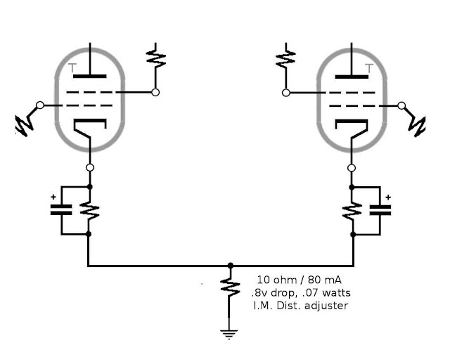
The circuit has to connect to the cathode resistor, see sketch below: outside the dotted frame is the existing circuit(1) The connections for v1 and v2 are those between the plate and cathode? This would need to be modifed to accurately measure current differences. I would not expect the tubes to ever have equivalent resistances except during instantaineous crossovers in transient variations.
I would rather measure the voltage/current through the fixed cathode resistor to ground for accuracy.
No, you can feed it with a ~20 -25mA current from anywhere.(2) Is the 300v tap necessary? On the one hand, I'll be using a 520 volt supply, and on the other, the HV seems unnecessary for a low voltage circuit connected near ground with an average voltage range of 50-120 volts (bias) and transients at the cathode hopefully not much higher than 200 v (?)
If the cathode voltage is as high as 120V, you will need other transistors.
It is just any LED I used for the sim.What is the QTL690C? just a part number for an ordinary red LED?
See above(4) Have you eliminated the sampling resistor across the cathodes in my circuit?
All the transistor are identical, they are preferably small, high gain PNP's, but if you operate at 120V you will need MJE350 or similar.will any small PNP signal transistors do here?
What is the meaning of the two different types of transistor?
But I would advise against it: it is preferable to split the cathode resistors to operate at a more reasonable voltage level, like ~12V or 15V.
That way, you will be able to use small transistors.
It would work, but its minimum Hfe is only 40, that is 1/10th of the BC's. It is preferable to use higher gains typesSpecifically, Can I substitute the following:
BC557C PNP GP 65v 100ma transistor: subwith a 2N2904 GP PNP 60v 600mA?
The 1N4148 must be the most common and cheapest component in the world, why on earth would you want to sub it?1N4148 GP fast Diode: sub with a 1N4007 (1000v)?
No, it is a 1A schottky, any similar type will do, but here again the 1N5818 is the most common 1A schottky available.1N5818 Rect. Diode 30v 1A: sub with a 1N4148 30 volt 1w zener?
The area of this diode will influence the center-band width (green LED):with a smaller schottky,,like the BAT54 or BAT85, it will be narrower, with a larger type like the 1N5820, it will be wider.
Any LED, any color to your taste will doQTLP690C superbright 20mA 5v LED: sub with std LEDs?
Attachments
Last edited:
As for subbing parts, two good reasons:
(1) I have limited parts in my box.
(2) I have no money.
(3) I live in post-industrial Canada, where every decent parts-store has closed down, because people don't build or repair anything anymore. They buy a new cheap replacement from China.
Your parts may be common in large American cities, but not here in my Igloo.
Also, thank you again for all your effort here,
both at providing a workable solution,
and also in explaining the issues and tolerances of substitutions.
This was a very rapid and professional response to the task.
I greatly appreciate your experience and advice here.
Nazaroo
both at providing a workable solution,
and also in explaining the issues and tolerances of substitutions.
This was a very rapid and professional response to the task.
I greatly appreciate your experience and advice here.
Nazaroo
This is a great idea. I can put 10% of the cathode resistor at the bottom, and tap from there, sampling about 12 volts out of 120v.But I would advise against it: it is preferable to split the cathode resistors to operate at a more reasonable voltage level, like ~12V or 15V.
That way, you will be able to use small transistors.
I can use precision resistors down there, and I can then have confidence that the current on each side is very close.
I have to ask just one more question:
1) Which resistor values are not critical and which have more narrow tolerances here for performance/malfunction issues? (I have a limited part-box).
Last edited:
The circuit is tolerant and will accept many alternative components. The types I have used as an example are very common and inexpensive, and they would be difficult to beat, but if you have other types of diodes and transistors in stock, the circuit can probably be modified to accept them.
Post your amplifier schematic, your voltage tolerance requirement and your preferred list of semi's, we will see how to make the best out of them.
Post your amplifier schematic, your voltage tolerance requirement and your preferred list of semi's, we will see how to make the best out of them.
Thanks!
I was thinking I could take taps as you suggest, splitting the cathodes into series-pairs (10% R precision at the bottom) for about 12 volts on either side.
If I do that, would there be anything wrong with taking the power from the top of the cathodes, by running a diode from each side to the center for a +ve supply?
The opposing diodes would not allow current across the cathodes, but using two would balance the current draw (?).
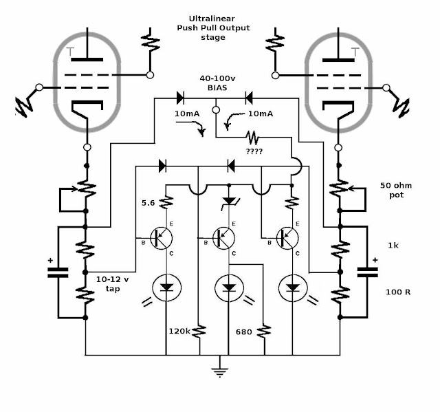
Okay here's the relevant portion of the schematic (the rest is still being designed).
I am suggesting getting power from the top of the cathode resistors, without interfering with them too much.
And taking readings off the top of a precision resistor bearing 10% of the cathode resistance (for about 12 v).
Now however, the top feed resistor will be unknown.
How should I calculate a safe value?
I currently have 2R2, and 10 ohm 2w,
instead of your original 5.6 ohm.
I had a 120 R 1%, and a 680 R 2w.
I have 1N4007s for 'ordinary' diodes,
and about 10 2N2904s doing nothing.
I don't think I have any Schottky 1A diodes.
Nor do I really know what they are for.
I have powersupply diodes and zeners only.
and a few different color LEDs, normal size.
I also have a dual color LED, but its not a three-color.
I have testbench powersupplies, and I am trying to think of
a test-circuit that would be able to confirm the new circuit works. (I don't need to hook up any tubes for that).
- Status
- This old topic is closed. If you want to reopen this topic, contact a moderator using the "Report Post" button.
- Home
- Amplifiers
- Power Supplies
- A simple PushPull balance LED indicator?