Hi,
I'm just building a Pass Xono. It uses 6 SLA's they output 2x38V to feed Paul Hynes regulators then.
For charging I regulate current to 0.5A and regulate voltage to +/-41.2V.
This charger is a floating one which carefully charge the SLA's while I'm not listening music.
I need your help urgently
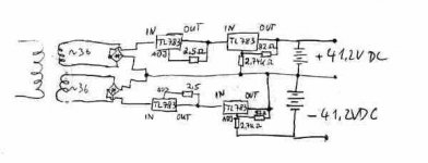
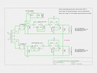
I'm not sure if my research is sufficient. I created a positive and negative regulation scheme with the TL 783. If someone is expirience of these things - please have a look to my sketch.")
A)I know that the trannies secondaries have to be separated ones.
B)The negative voltage part is coming from the adjustment pin and the output is grounded.
C) I'm not 100% sure about the current regulation, but as far as I renember its the same as positive ones.
D) As I use 0,5A current...how should it come out of the 2,7K resistor????
Jochen
I'm just building a Pass Xono. It uses 6 SLA's they output 2x38V to feed Paul Hynes regulators then.
For charging I regulate current to 0.5A and regulate voltage to +/-41.2V.
This charger is a floating one which carefully charge the SLA's while I'm not listening music.
I need your help urgently
I'm not sure if my research is sufficient. I created a positive and negative regulation scheme with the TL 783. If someone is expirience of these things - please have a look to my sketch.
A)I know that the trannies secondaries have to be separated ones.
B)The negative voltage part is coming from the adjustment pin and the output is grounded.
C) I'm not 100% sure about the current regulation, but as far as I renember its the same as positive ones.
D) As I use 0,5A current...how should it come out of the 2,7K resistor????
Jochen
Attachments
Hi,
I checked your resistor assuming that you have a 50 volt power supply the resistor should be 2700 ohms. That will give you a voltage output of 42.43553659 volts. I used the Tl387 in all of my voltage regulators power supply. My advice to you is to use a fixed 2000 ohm fixed resistor and 1K variable resistor for fine adjustment. Remember the resistor are not 100% the value they are marked.
I checked your resistor assuming that you have a 50 volt power supply the resistor should be 2700 ohms. That will give you a voltage output of 42.43553659 volts. I used the Tl387 in all of my voltage regulators power supply. My advice to you is to use a fixed 2000 ohm fixed resistor and 1K variable resistor for fine adjustment. Remember the resistor are not 100% the value they are marked.
A constant-current, constant-voltage charger is not a float charger as far as I know. I could be wrong. To me that sort of circuit is good for a constant load, and a battery charger expects anything but.
Don't your batteries have a spec'd float-charge voltage (perhaps called "stand-by", as opposed to "cycle")?
addendum: If I remember correctly, SLAs like to charge via a constant voltage, then when nearing full-charge, switched to a constant current maintenance charge.
Don't your batteries have a spec'd float-charge voltage (perhaps called "stand-by", as opposed to "cycle")?
addendum: If I remember correctly, SLAs like to charge via a constant voltage, then when nearing full-charge, switched to a constant current maintenance charge.
Last edited:
I think that 41.2 V is OK for 'Float Charging' Sealed Lead Acid Batteries. Though any cell imbalance isn't going to be good. Ideally if you intend to discharge the batteries it would be good to increase the voltage for a boost charge for a period but needs a more sophisticated control circuit to avoid overcharging and hence shortening the life of the cells. Without the boost charge the cell life will be shortened due to undercharging.
I was going to suggest something like the Texas Instruments (Unitrode) UC3906 but it is limited to 40V.
I think that your schematic is wrong for the - 41.2 VDC. It needs to be the same as for the +41.2 V but with only the voltage control TL783 OUT terminal connected to the junction as you have drawn.
I also note that there are no smoothing capacitors on the input so there will be high ripple current through the batterries during charging which might be detrimental. The second TL783 voltage regulators might go unstable without a capacitor connected to the input.
Last edited:
Hi tauro0221 & sofaspud,
thanks for the comments!
Yep the poti will be implemented. The 2,7K is just a rough value, I'll fine tune this to exactly 41.2V.
*
The charger is a "stand by" type - I' ve studied Panasonics SLA spec.I meant this with "Floating".
SLA get charged by appr. a 10th of their main capacitance. I have 12V 7Ah Yuasa batteries and I use 0.5A. For voltage its common to use 14.2V in cyclic mode but in my case its too much.
When I stop listening to music my Xono circuit is still left "on" but in this case supplied by the carger supply + batteries. Means my batteries get charged continously until I get back to music. So I chose a lower voltage = 13.7V for charging. This voltage avoids aging effects of the SLAs as good as possible.
Current is just "limited" in my case ...the SLAs take as much they need depending on their charging status.
I've identified that my negative rail CCS needs to be a current sink - thus IN and Out pin needs to be reversed.
Jochen
I think that your schematic is wrong for the - 41.2 VDC. It needs to be the same as for the +41.2 V but with only the voltage control TL783 OUT terminal connected to the junction as you have drawn.
Hi PCHi,
thanks to you as well for helping!
I don't understand what junction you mean? Could you discribe it again?
*
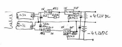
For the "boost charging" you maybe right...
 but I guess the inbalance is much more critical over lifetime.
I updated my sketch
Jochen
Attachments
Last edited:
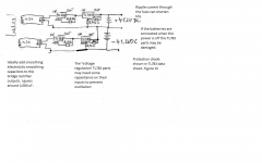
I have modified the schematic to what I think will work, no guarantees though.
Thanks PChi
I guess I have to try it out now!
Still I'm puzzled about the 2.7K "output" can't imagin how this can work...

Sorry but confusion: I left out the caps for simplicity ;-)
Jochen
Last edited:
Final Sketch
Hi,
so I guess I have it now - I'm going to try it now.
Thanks for your help.
BTW: I use 2000 to 5000µF for the first cap and probably use a 10 Ohm resistor before to avoid too hard current impulses which harm the lifetime of my switch.
I also understood more about this negative regulation with a positive IC. You can read this http://www.diyaudio.com/forums/blogs/wintermute/225-yarps-yet-another-regulated-power-supply-updated-2012-01-02.html
Jochen
Attachments
My 6 battery charger isn't stable!!! Where is the problem ? HELP
Hi guys,
its been a while since I could come back to my Pass Xono project.
I soldered everything now. I switched it on and first I was lucky.
I got + / - 42V charging output as desired - Ok but I didn't had a load connected.
Just for a dirty test I connected two 180Ohm resistor at the charger outputs, simualting a batttery load:
Result my voltage drops significantly!!!! to 10volts both the negative and positive side
(... at least both rails behave identically)
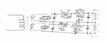
-> Can you help me again? I attach a schematic. I know that my Rset (42K) for negative voltage rail is way too high but the value was set by trail and error.......
-> Do you see any explanation why my circuit isn't stable? what should I do now
thanks in advance - Jochen
Hi guys,
its been a while since I could come back to my Pass Xono project.
I soldered everything now. I switched it on and first I was lucky.
I got + / - 42V charging output as desired - Ok but I didn't had a load connected.
Just for a dirty test I connected two 180Ohm resistor at the charger outputs, simualting a batttery load:
Result my voltage drops significantly!!!! to 10volts both the negative and positive side
(... at least both rails behave identically
)-> Can you help me again? I attach a schematic. I know that my Rset (42K) for negative voltage rail is way too high but the value was set by trail and error.......
-> Do you see any explanation why my circuit isn't stable? what should I do now
thanks in advance - Jochen
Attachments
Hi,
Why you need the current regulator? I will remove it. At the beginning when the battery voltage it is lower than the 41.2 the current will be high but as the battery voltage increase the current will decrease, When the voltage are the same it will have a small current going to the battery. It will adjust itself.
Why you need the current regulator? I will remove it. At the beginning when the battery voltage it is lower than the 41.2 the current will be high but as the battery voltage increase the current will decrease, When the voltage are the same it will have a small current going to the battery. It will adjust itself.
Hi,
Why you need the current regulator? I will remove it. At the beginning when the battery voltage it is lower than the 41.2 the current will be high but as the battery voltage increase the current will decrease, When the voltage are the same it will have a small current going to the battery. It will adjust itself.
Hi Tauro,
Thanks for your suggestions again! I will check pin 3 ...proably its already my problem.
For the current reg: The batteries should get a tenth of their capacitance = 7.2Ah means charging with max 0.7A. That is my logic here. But somehow you are right my toroid can draw 3.5A max means 1.75A per rail. The Batteries won't discharge that much anyway as they a usual listening session isn't able to discharge them significantly.
Good idea to simplify the circuit
Did you ever built a negative TL783 circuit? I'm really wondering about the Rset=42KOhms
Jochen
Hi,
I used it a lot for pos/neg power supplies but I used the 82 ohm for the R1 and used the equation to calculate R2. Another suggestion it is to let the battery discharge and then charge it while monitoring the current to see where the battery current stop. Then raise the voltage a little to maintain a trickle charge.
I used it a lot for pos/neg power supplies but I used the 82 ohm for the R1 and used the equation to calculate R2. Another suggestion it is to let the battery discharge and then charge it while monitoring the current to see where the battery current stop. Then raise the voltage a little to maintain a trickle charge.
- Status
- This old topic is closed. If you want to reopen this topic, contact a moderator using the "Report Post" button.
- Home
- Amplifiers
- Power Supplies
- Help! Battery charger +/- 41,2V with TL783