I am surprised at the accuracy of the charging voltage requirement for maintenance charging.
They state and give the temperature correction of -3mV/C.
Does the C refer to case temperature, or electrolyte temperature, or plate temperature, or some other?
To obtain precision, it seems that a 10 C degree error uses up more than half of the tolerance for the maintenance charge voltage.
How do we determine the precise Maintenance charge voltage for a particular battery, let's say the one I have on charge in front of me?
Andrew, again the accuracy of charging is all to do with battery life. No matter how small a current trickles into a battery at some instance it will boil the battery electrolite - a term not to be confused with high temperature but bubbling, and giving off gasses. These gasses, if it is in a sealed battery has a specially designed case that would cause them to be reabsorbed into the liquid/gel in time. However should this continue the seal will blow and the gasses will be lost into the air and eventually "boil" dry.
In a flooded cell, one with caps you can replenish the electrolyte with distilled water, thereby keeping it from "boiling" dry.
Finally you will find that dV/dt has a very close relation to electrolyte temperature and the higher the temperature the faster the battery will charge. Finally millivolts and a degree centigrade does make a difference if it will keep your Euro10 000 battery from dying a few years before you expected it.
this interpretation seems to be at odds with the philosophy of maintenance charging.No matter how small a current trickles into a battery at some instance it will boil the battery electrolite - a term not to be confused with high temperature but bubbling, and giving off gasses. These gasses, if it is in a sealed battery has a specially designed case that would cause them to be reabsorbed into the liquid/gel in time. However should this continue the seal will blow and the gasses will be lost into the air and eventually "boil" dry.
Maintenance charging is injecting a continuous current for an indefinite period such that the battery does not "gas" and neither charges, nor discharges, i.e maintains the "full charge".
Another charger design question.
I am familiar with the 3stage charging, i.e Constant Current, to Constant Voltage to Maintenance charging. This is relatively easy to design and build without microprocessor controllers.
The Question.
What alternative "analog" solutions are available to detect and change the CV (stg2) mode to M (stg3) mode?
Detect the actual CV mode current and switch over?
Detect/read the time on stg2 and switch over?
Others?
I have always used the 10hr capacity as the CCS charge rate i.e. a 60Ahr battery charged @ 6A for about a day gets upto the CV limit and automatically becomes CV mode, where I leave it for about 2days. I see that many of these links are suggesting much higher rates of charge and that necessarily enforces much shorter charging periods to avoid gassing.
Is my "slow" version of CC then CV doing the battery damage, or is it simply a "safe & reliable" way to charge and maintain longevity? But takes a lot longer?
I think I have answered some of this in a previous thread but lets look again where these set points are. There was also a mention in a previous thread of what the different battery make-ups require they cannot all need the same voltages and you are right they don't but if you are making your own charger it is easy you are making it for a particular battery and a particular strategy - which of course you choose.
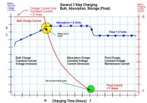
Look at the attached graph and you will see the two break-points used for the transition from constant current to constant voltage and then to float or equalisation or switch off whichever you please.
All batteries have theses characteristics as they are chemical reactions and you can detect them quite easily by many means.
To answer your last question Andrew, it does not matter if you charge a battery slowley or fast or very fast for that matter all you need to observe are these set-points because they will be there.
There are some charging strategies and we make such chargers as well which is purely time based and consists of say an 8 hour and a 4 hour rate but these are for specific applications such as a forklift battery and you have a particular charger set up for a particular battery type and the forklift operates until the low battery light comes on and then it goes to be charged.
EDIT: Typically a good battery requires about 120% energy for recharging - if you require more then the battery is starting to age up to a point when there is no useful remaining life and time to scrap it.
If I can be of any more help you are welcome.
Attachments
Last edited:
this interpretation seems to be at odds with the philosophy of maintenance charging.
Maintenance charging is injecting a continuous current for an indefinite period such that the battery does not "gas" and neither charges, nor discharges, i.e maintains the "full charge".
So what are you saying because it is just that - maintenance charge trickles just enough current to counteract the self discharge of the battery, caused by many things.
If you just leave a battery standing, it will go "flat" unless you maintain its charge with a few mA. Some chargers provides a maintenance charge that produces enough current to maintain the charge while some appliance is connected, for example a car ECU or a clock, so maintenance charge to different people mean different things. Maintenance charge requirement for a guy who has a lot of vintage vehicles means that each individual charger is set for that particular vehicle. Maintenance charge is not a necesity if you cycle the batteries often and they are not under constant load draining them. Thus these multifacetted multi featured chargers are sometimes more evil than what you will ever need need.
Maintenance charge for Daniel for instance means the charger switches off for a few days. Some strategies are pulsed float charge, in other words it allows the battery to self discharge to a set point and kicks in charging at full bore for a few seconds and turns off monitoring the battery. Some say this is better for some sealed batteries and others don't. There are no general startegy and your requirement would dictate the charging strategy.
Last edited:
re post63.
The change from CCS to CV charging, shown in the yellow highlighted circle is easy to engineer.
It's just a CCS regulator feeding a CV regulator.
The battery voltage rises until the CV limits the charging voltage. The CCS also acts as a convenient short circuit protection.
It's the green highlighted CV to M charging that I can't see how to do easily.
Would timer or current limit be better, A window comparator detects the lower current limit and switches the CV mode to a lower M mode. Or should it be both? Where the current limit is set and then a timer allows a maximum time for the CV period and "times out" even if the lower current limit has not been reached and changes to the lower M mode voltage.
Hi Andrew, we detect current (voltage actually) across a shunt to determine in general that the current dropped to less than 100mA in a typical 10 amp charger (typically 1%).
The shunt is just part of a PCB track so nothing exotic. There is one point that I would like to make and that is a faulty battery current may never drop to this value for some reason such as some dick filled it with tap water which is actually conductive because of the chlorine and other salts in it to make it safe to drink.
In this case one would like to add a safety timer that will force the charger to end the constant voltage stage after say 6 hours. (what-ever you feel safe with).
What I am saying is either your reach 100 mA or the timer exists CV and then follows float or switching off the charger completely.
Many chargers strategies is to run CV stage for 1/2 to 1/3 of the time it took to reach the CV changeover point and not bother with a current threshold.
Looking at the various curves which is taken from practical measurements you can see this 2/3 and 1/3 of total time rule of thumb quite easily. Point is when you reached the end of constant current a battery is about 80 - 85% full and the CV stage only achieves the remaining 15 - 20% if the battery is in good condition. In a battery that has lost electrolyte, CV sometimes does nothing since the plates are exposed and not covered by electrolyte or sulphated so badly that reduces the active plate surfaces similarly.
Last edited:
Thanks for your participation AndrewT your questions prompted some useful dialogue to the members here.
There is no magic in battery charging, but there is a little thought and care required to extend your battery's life to the maximum. every application would require a slightly or even vastly different charge strategy. Even manually charging your battery may be the best option in many cases.
If you are the type of guy that only needs to charge your car battery on occasion during winter almost any charger will do, even if it is non-automatic simply because you can hardly overcharge it overnight, besides it is cold which will limit the absorption anyway.
However, if your life depends on your battery, you will think very carefully what critical aspects of the charging strategy you need to apply to maximize the battery life and maintain its capacity.
The rule of thumb (that Andrew mentioned) is to charge your battery at about 1/10 of its 10 hour capacity overnight. In other words 12 hours using a 6.5 - 10 amp source for a 65 Ah battery is absolutely perfect.
What some do not realise that many battery manufacturers use different specifications and quote a 20 hour rate. This does make the "same size" battery seem cheaper.
So make sure to look at the amp hour rate quoted on the battery, don't take the salesman's word for it, he might not know either.
Last edited:
I don't know if the battery knows the difference, but all these charging strategies are based on continuous and non varying DC current charging.
A normal car battery charger is a rectifier and transformer. That cheap battery charger uses pulses of varying current to charge the battery.
I have used these cheap chargers for decades on car batteries and we all know they don't last decades.
Is it the bad charging that kills them, or the attempts at drawing hundreds of amperes out of them when they are very cold and only holding half charge from last night's heated rear window journey, or the alternator overcharging the battery repeatedly after every start?
And why do the oem car batteries always seem to last way longer than those in the replacement car battery market?
Andrew, from experience I will tell you that the replacement battery that you purchase from the aftermarket fitment centre has been sitting on a shelf for months and sometimes even years and have not been maintained at all.
I have seen "new batteries" not capable of maintaining its capacity for any length of time. The worst one can do is store a half charged battery. Unfortunately some think that a charger can fix a sulphated battery, I assure you all it cannot.
There are some wizard companies claiming you can desulphate a battery by using a high frequency AC on the battery. While it may be possible to "shake off" the sulphate the battery plate is now smaller and cannot store or retain the energy specified.
OEM battery stock is used up on a daily basis as it is built into cars and the dealer has been told to maintain the battery while on the showroom floor because there is no way that the OEM wants to replace batteries before the vehicle warranty or service agreement expires. This is probably the best reason one could supply for the kind of experience you are quoting.
Last edited:
That is because of the energy usage and heat output and noise output of the RV's old style AC converter charger.Maintenance charge for Daniel for instance means the charger switches off for a few days.
For solar, it is less of a concern, because that automatically turns off every night, so there's less chance of battery wear and it doesn't cost a huge amount to run a solar panel.
")
Together, the goal is that the AC charger doesn't turn on until the battery discharges to ~12.6vdc. I measured how long the little loads take to pull down the battery that far and it is about 2 days. If this AC charger could be outfitted to switch off at 13.5vdc and await 12.6vdc before switching back on, then it would almost never run IF a solar charger is used concurrently to keep the battery better than ~12.6vdc.
However, I do find it necessary to retain the AC charger since there is a heater blower and other motors that when and if used could flatten the battery down below 9v, causing damage. So, that's a good time for the high current AC charger to awaken and help out.
Currently, Elvee's circuit works brilliantly for a charger that outputs clean DC; but that is not the case with my half wave charger. The circuit detects the 18v of noise causing it to repeatedly fire the disconnect relays. So, I'm stuck. Well, I still need a 10A charger that will "sleep" (power saver) after it has charged the battery no higher than 13.5vdc and awaken when the battery reaches 12.6vdc.
Last edited:
Daniel that is exactly what the schematic of #55 does. Your set the two threshold voltages and it will switch off when it reaches the upper threshold and turn on again when it falls to the lower threshold.
Thanks! What voltage and amperage transformer, and what SCR are recommended for 10a charger?
Other problem is that I don't see all of the connections for the voltage comparators.
Schematic confusion:
U1A doesn't list where to connect V+
U1B doesn't list where to connect V+, Output
U1C doesn't list where to connect In+, In-, Output, but one might hazard a guess that V+ and V- power connections are maybe possibly shown for that one, but I'm not sure.
Is U1C actually not a voltage comparator but merely the power hookup for U1A/B dual voltage comparator chip? If so, then the remaining mystery would be the output connection for U1B.
Ah. . . Help?
I will post the whole charger here when I am back at work. You want the PCB as Gerber plots or PDF plots? Or do you want a bare or populated and tested PCB by post. A transformer for your battery needs selected in other words if you have 100 Ah battery select a 10 amp at 12V rms transformer. If you want to charge slower halve the current. Longer lower current charging cycles results in more energy being absorbed and less dissipated as heat.
This is a simple charger and does exactly as per your requirement it does not follow the charge curves as explained earlier.
This is a simple charger and does exactly as per your requirement it does not follow the charge curves as explained earlier.
Last edited:
Thanks! What voltage and amperage transformer, and what SCR are recommended for 10a charger? The PCB layout is for a typical 3 amp unit. Use a 10 amp transformer and 10 amp rectifier for 10 amps. The SCR is BT151-650.
Other problem is that I don't see all of the connections for the voltage comparators.
Schematic confusion:
U1A doesn't list where to connect V+ The power gate U1C is at the bottom right hand corner of schematic.
U1B doesn't list where to connect V+, Output as above U1C doesn't list where to connect In+, In-, Output, but one might hazard a guess that V+ and V- power connections are maybe possibly shown for that one, but I'm not sure. ... that is the supply gate to U1, the other two gates U1A and U1B. Only a single comparator in the package is used U1B is spare.
Is U1C actually not a voltage comparator but merely the power hookup for U1A/B dual voltage comparator chip? If so, then the remaining mystery would be the output connection for U1B. No mystery, U1B is not used. Just comes to show how simple this charger really is.
Ah. . . Help?
Last edited:
I guess this is not a Lead-acid battery? If it was then there would be no point in turning the charger off, just ensure that it has a properly temeperature-compensated float voltage. The temperature sensor needs to be a remotely connected one so that it can be attached to the battery (or batteries) under charge.
A Ni-Cad or Lithium rechargable battery pack will need to be disconnected when the batteries reach full charge, but each of these battery technologies require their own dedicated charger.
The commercial units use a tiny 8-pin microprocessor. These cost about as much now as an opamp. the uP needs three analog inputs to measure voltage, current and temperature and one analog out to control the power supply.
Another input might by a few swiches so you can tell the uP what kind of battery is connected, gel, AGM or flooded.
You should be able to run the microprocess off the power from the battery it is charging, so it can monitor voltage and re-connect to AC power as required. Some of them can run on just a few micro-amps
Last edited:
@Nico,
I wish I find where to buy the little smart six charger:
I wish I find where to buy the little smart six charger:
An externally hosted image should be here but it was not working when we last tested it.
- Status
- This old topic is closed. If you want to reopen this topic, contact a moderator using the "Report Post" button.
- Home
- Amplifiers
- Power Supplies
- Float charger? Cut off at 13.5v rest until 12.5v before switch on?