A CCS feeding a voltage regulator.
Make the current setting of the CCS adjustable/switchable.
Make the voltage setting of the regulator adjustable/switchable.
A nice clean CCS feeding Elvee's circuit works very well. That gives the longer cycles to avoid battery wear and spends day(s) at a time with zero consumption (electricity bill). I was quite impressed with it set up like that.
But the current of a solar panel is unpredictable, I need to charge a small cap first to assure good voltage output and this could cause relay chatter or wear from the pulse, so I need to replace the relay with solid state switch. I'm trying to do it, but have not yet quite managed.
If the solar cell has too little voltage then it is not ready to start charging.
If during that time the relay refuses to pull in then great. That matches solar availability.
As for relay chatter. Design your pull in voltages correctly. Use a cap across the [relay coil+transistor switch].
If during that time the relay refuses to pull in then great. That matches solar availability.
As for relay chatter. Design your pull in voltages correctly. Use a cap across the [relay coil+transistor switch].
Smart 6 Charger, finding a transformer for it.
The board for the Smart 6 charger is coming and I need to find a transformer for it.
Option 1
So far, I have found a large size 14v 56va EI Core transformer. My line voltage is 120, not 110, so the output is quite close to the 15v. Well, that's the free option. It is appears to be able to actually withstand 80va use (about 5a max). With the large size of it, it should be able to dissipate heat well.
Option 2
Here's the non-free option: http://www.antekinc.com/pdf/AN-2215.pdf
At the bottom of the PDF is secondaries in series test at 120v input, with the normal operating range listed as 15.3v, 6a.
I don't really know which to choose.
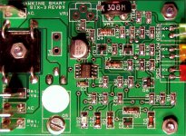
Photos! Hawkins board!
Earlier this week, the Hawkins Smart6 Charger board arrived. Looks nice!
It appears to have the needed voltage adjustments aboard, but not the current capacity. The Smart 6 is actually a 3 ampere unit.
I received directions that I was to use a stronger bridge rectifier and stronger transformer. I can provide an input of 15vac 5a, but I don't know how to set the charger output for 5a. Any ideas?
I can't find the current limiter setting.
Schematic is here.
Attachments
Hi Daniel, all you need to do is change to a larger off-board diode bridge, the the SCR (BT151) is good for 10 amps. The reason I sent you this charger is that it is the simplest one that we have and locally a 25A bridge will probably cost you less than a Dollar.
I am PMing you some contact information.
I am PMing you some contact information.
With a 50 ampere transformer and 50 ampere bridge rectifier, the output is 3 amperes, because. . . The board's current limiter is set for 3 amperes.Hi Daniel, all you need to do is change to a larger off-board diode bridge.
I need 5 amperes.
So, I have emailed as indicated and await news on how to set the current limiter for 5a.
Hawkins tech support responded.
I was incorrect.
This device is current limited by the transformer itself.
Removing some of the headroom by using the 3a charger for a 5a charger is not very convenient.
It is not difficult to push a healthy battery up to a voltage; however, if the battery happens to have a load applied during charging (in my application that is likely to occur at random) then the transformer has to pull down well before 10a or else the SCR is exceeded. I'm definitely putting an autofuse/ShortStop (automated circuit breaker) on this situation!
Now I'm guessing, but because my application is about a volt lower than intended, perhaps the 14vac transformer is the safer option than the standard 15vac.
It seems that the bridge rectifier participates in the current protection scheme, making Fairchild Stealth the best option (0.3v to 2.2v vdrop). However, anything with a pronounced curve might do, like KBPC1610 (max) or KBU808 or KBPC4010. Any 800v to 1000v diode with relatively low amperage will lay over 1v or more, thus helping to match the input voltage to the output voltage before passing 10 amperes. The transformer does most of that work, but yet I shouldn't install a KBPC2502, since that is not so helpful.
Still trying to figure it out.
Last edited:
So far, we've determined to employ a 5 amp autobreaker just in case I guess the wrong transformer selection: 5 Amp 12 Volt Automotive Circuit Breaker, Short Stop
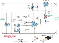
Charging controller cct
This any help? It's from the "circuit notebook" section from the Aussie Siliconchip magazine, August 2008.
From the description:
This simple charging regulator circuit is connected between the charger and the battery and is easily adjusted to prevent the battery being overcharged beyond the optimum level between 13.8V and 14.0V.........As soon as the battery terminal voltage rises to 13.8V (or the preset voltage), TP1 rises above 7.2V and this causes the output of IC1 to switch high. The current through LED1 falls to zero and Q1 is switched off, preventing any further charging. The 47kW resistor between pins 2 & 7 of IC1 provides about 0.5V of hysteresis so that the battery voltage will need to drop by 500mV or so, before the circuit can turn back on to provide more charge.
Silicon Chip Online - Circuit Notebook
Attachments
Last edited:
Thanks Marcus! Finally some documentation about correct battery charging voltages and cycling. I'm really grateful to see that. It can protect the Marine/RV/Industrial "not a start battery" types.
Quick, everyone look at the footnotes in red. 13.8v max. That is true, except for "car start" batteries.
Quick, everyone look at the footnotes in red. 13.8v max. That is true, except for "car start" batteries.
Last edited:
Daniel,
that charging information comes from the battery manufacturer.
Do not expect the charger manufacturer to know what every manufacturer and every model from each of those manufacturers needs as a charging requirement.
Go to your battery manufacturer and ask them what your battery needs !!!!!!!!!!
that charging information comes from the battery manufacturer.
Do not expect the charger manufacturer to know what every manufacturer and every model from each of those manufacturers needs as a charging requirement.
Go to your battery manufacturer and ask them what your battery needs !!!!!!!!!!
That's really good advice that should have worked. I tried that. Hawkins tried it too. The battery manufacturers respond with typical car battery specs or sometimes just no response.Daniel, that charging information comes from the battery manufacturer. Do not expect the charger manufacturer to know what every manufacturer and every model from each of those manufacturers needs as a charging requirement. Go to your battery manufacturer and ask them what your battery needs !!!!!!!!!!
The "slow drain" type of batteries, a "not a start battery" huge marine/rv/industrial type, all measure to resist charge and get really hot at 13.5v when new or 13.8v when older. They all run down to about 12.5 when new or 12.8v when older, if left unattended for a few days. Car alternator voltages and the higher current chargers from the auto parts store all break this type slow drain battery--it is not a car battery. The expense is terrible. But, the 1a transformer limited trickle charger doesn't break the battery and the weak solar doesn't break the battery. This would be okay except for a boat or RV that has appliances.
With a boat/RV's onboard converter-charger that does right voltage but never lets the battery idle/rest, the energy bills for slowly destroying batteries are about $40 per month and this in addition to battery replacement costs of about $130 yearly. So, the approximate average yearly waste is: $610, and $130 of that (subtract retail store margin) is unfortunately profitable for the battery manufacturers. SO, both the store and manufacturer profit from this problem at regular and expected intervals.
I said a bad word when the battery manufacturer told the battery charger people to charge the "slow drain type" batteries at breakage voltages. Although you could probably do it, if disconnecting the charger, the prospect, based on wrong data with no real-life measurements, is financially very unpleasant for nonstop maintenance charge. The typical electricity bill for abusing batteries nonstop is about $40 per month; however, if it is not charged, the circuit boards of the charge monitor, radio and fridge will eventually pull the battery down lower than 9.5v damage threshold for yet another way to break the battery. An additional method is allowing a non-full battery to freeze, which also breaks the battery.
This is an expensive problem with so many ways to break the battery!
For charger, I dreamed a low cost version--15v 90w laptop power pack, diode for reverse voltage protect, Elvee's voltage regulation circuit and 3 parallel 18w #1156 light bulbs for 54w current limiter. But that would be too easy! Yay for simple vacuum tubes/valve diode current limiter! lol!!!
Last edited:
- Status
- This old topic is closed. If you want to reopen this topic, contact a moderator using the "Report Post" button.
- Home
- Amplifiers
- Power Supplies
- Float charger? Cut off at 13.5v rest until 12.5v before switch on?