What I see here reminds me of my life as college undergrad. I had some fantastic EE professors who saw potential in me and stuck their foot in my behind whenever I performed at less than their expectation of my capabilities. I didn't appreciate it until I was a junior and really began to see the fruits of their efforts and what it would mean for my future.
I see some of the "noisy" people here (like Fred) as doing the same thing. For this stuff, you understand it by fighting to wrap your brain around it. Sometimes it's more of a struggle than at other times. Some of us have learned - reading helps....
A lot....
As Nike says, "just do it"
mlloyd1
(who puts his foot down whenever the wife says "why are you keeping those old The Audio Amateur magazines?")
(and who also:
1. waves "hi" to Walt,
2. still enjoys the super regs says (Thanks Walt!)
3. can personally vouch for him being a VERY helpful and VERY knowledgable guy for much more than super regulators!
Christer said:.... So if someone asks without reading up, and it irritates you,
the solution is simple -- just don't bother to answer. [/B]
Actually, you folks act kind of silly, but please don't take offense. Weeks ago, I invited Walt Jung over to this website. Please, let him want to join in and teach us a thing or two. ;-) . When 'we' contribute to magazines, we usually expect people to use our designs, but we like to get credit, when it comes up at a place where it can be put in print.
I don't know the legal aspects of copyright, but I would love it, if I could sue anyone who has copied and built what I have published in the past. Who would need patents then?
I don't know the legal aspects of copyright, but I would love it, if I could sue anyone who has copied and built what I have published in the past. Who would need patents then?
Christer,
This IS a very interesting topic, it's groundbreaking. This together with Jean Hiraga's work ( well for the European audience that is) this could have given anyone a headstart already so many years ago.
Just don't ask me in public as to why the US has taken twenty years to pick up on this...
It wouldn't surprise me if they'd make claims to intelectual property either...
Indeed...I wonder.
__________________
Frank
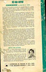
US claiming IP on feedback regulators? Why not? For example, see the 1946 MIT Rad Lab series #21, "Electronic Instruments", section 16-6, 'Practical Regulator Design / Precision DC Voltage Supplies', in Fig. 16-27 for example. A tube based feedback regulator with the VR105 reference tube fed from the regulated output. A 6SL7 differential input amplifier is used, with a 6Y6 pass tube. This section was authored by A. Jacobsen and J. V. Holdam, Jr.
This clearly predates any solid state/op amp based feedback regulators, which as far as I know came about in the 1960s and 1970s. It is very interesting to see just how much the early technology had been optimized. The circuit in question had an output impedance of 0.8 ohms, and a regulation of 0.05%. But these were serious times indeed, there was a war ongoing.
Don't look for this work online (except perhaps a purchase via www.abebooks.com , where I got my copy). Not everything of value exists on the internet, and never will. Some very good stuff still takes some hard work and digging. When one goes through this process, the knowledge gained and subsequently absorbed has greater staying power than that which is simply dropped into one's lap.
Walt Jung
AMEN!
"Not everything of value exists on the internet, and never will. Some very good stuff still takes some hard work and digging. When one goes through this process, the knowledge gained and subsequently absorbed has greater staying power than that which is simply dropped into one's lap."
This is why I frequently visit the engineering section of my local used bookstore. I also wore my boss out ordering books in my last telecom job. Someone stole my Horowitz and Hill and I am still furious. I let a copy of Henry Ott's "Noise Reduction Techniques in Electronic Systems" get away from me at the used bookstore because i was stupid enough to think i would pick it up on my next visit.
How about a list of your favorite Analog text and articles from beginner to advanced, in a new thread Mr. Jung? I expect you to include a couple of your op amp books of course and I post the titles if you are too modest. A word of warning though, modesty is a rare affliction on this forum, except for Nelson Pass of course, and we expect him to recover sometime in the near future......
Well Done
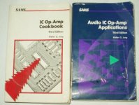
This Walt Jung book has been well used and much appreciated. There no longer a front cover, that came and went over 20 years ago. I purchased this book about 1978 and did help me out of many a problem.
Thanks Mr. Jung for all the good ideas.
This Walt Jung book has been well used and much appreciated. There no longer a front cover, that came and went over 20 years ago. I purchased this book about 1978 and did help me out of many a problem.
Thanks Mr. Jung for all the good ideas.
Attachments
Only the front cover... that's nothing!
I bought it about the same time as you. Mine had 'home made file folder' front and back covers before it completely disintegrated from use! My third edition has plenty of miles on it and my Audio IC Op Amp Applications is shedding pages from the chapter on Equalized Amplifier and Active Filters. This book and a few Spice models saved my butt when designing filters for a telecom answer supervision board. We even got our benchmark test of calling Honolulu for the volcano report to finally work every time!
'Read it to shreds' Fred
Attachments
Hi Walt, hope all is well with you! Jan Didden
Hi Jan, many thnx for the well-wishes. As you can see, they have me busy here, talking about the new/old regulators.
Hope all is well with you and yours...
Walt
> we have a number of professionals and advanced amateurs who have a lot of theoretical and practical knowledge to share with us, if they don't mind doing so.
Threads like this, with more noise than information, make such people "mind doing so". After this morass, Walt might decide to stay away from ALL forums.
> Some of these people are well reputed designers, which should give them a high credibility
All respect to Walt Jung and John Curl: commercial fame should cut little ice. Maybe the "Famous Designer" is just very good at selling so-so products? Maybe he's the front-man for a genius he keeps locked in the cellar? That has happened, a lot.
(Actually, my respect for Walt's writings is deep. The OpAmp, Audio, and Filter CookBooks are superbly concise, clear, and as complete as can fit inside covers. Sorry, I know less of Curl's work, except his products are well-regarded.)
> for some others we basically only have their own claims of competence.
Anybody who boldly claims competence probably wishes he had more.
The true guru will sketch-out the path, at a level that the questioner can handle, and let the student explore the landscape with just a few more hints. We who read the guru's words should not ask "who is this guy?", but "does this understanding mesh, in some useful way, with my understanding?" Or to put it more crudely: a BullPoop detector. The teacher can sometimes know less than the student overall, if he has a single insight into something the student is "not getting".
If you read through and of Walt's EDN articles, you don't have to know who Walt is. He explains enough that any truly interested reader can understand the concept and work out the details, and decide if the idea is crap or not. Now, Walt happens to be an exceptionally good writer (part talent, but a lot of practice) so he can say in two paragraphs what it might take some of us a whole page to cover. But we can type that page, and let readers decide if the idea is crap or not. There are a number of people here who have thoughts about things just as valid as any Famous Designer. We should discount the person (and any writing difficulty) and look at the idea.
> I do want a convincing argument
I added emphasis because those two words MUST go together. There is plenty of "argument" in this thread, but I don't see much or any "why" (convincing) about the regulator topology Peranders put before us. In fact I don't see any data or guess-work about start-up time, and only my quickie about dropout behavior.
I posted only a "quickie about dropout behavior" because I knew Peranders has the expertise to see the situation himself (a lot faster than he could read through the noise in this thread), and just needed a "poke" to move his thinking. Yes, I am aware that Peranders sells stuff; but I very much doubt he is "getting rich" from selling a few boards and parts. Anybody who has tried that knows that after tooling expense, order-site setup time, and hours of order fulfillment, the nett profit is about ZERO. Peranders basically sells a few to cover the tooling cost of building one for himself. Any notion that we should not help for free just because "he sells" is misguided. And repeatedly refusing to help simply clutters the board.
> I do think one should also try to spur them to read up on at least some basic stuff like Ohms and Kirchoffs laws.
This baffles me. WHY would anybody expect any electric thing to work, without the very basic understanding of volts, resistance, and current? OK, you plug in a lamp, or you assemble a kit, without knowing what's really happening. But I see people on forums like this trying to compare different alternatives, or tweak a circuit, when they can't guess "12 volts across 22KΩ". To my thinking, you can't look at circuits unless Ohms Law is "a reflex": you look at 12V and 22K and instantly think "about a half milli Amp". And while I don't consciously invoke Kirchoff too often, any time one wire splits into two it is old Kirchoff who will tell me (again more by reflex than thought) about how much current will flow up each wire.
At a more advanced (yet necessary) level: it is reasonable that most transistor workers can't cite Ebbers-Moll (large-signal transistor equations), but I'm shocked how many are not aware of Shockley's Relation (transistor Gm versus Ie). Not by name of course, but you should be aware that any silicon transistor's transconductance can be known just by knowing its current. I can't see how you would design without that information. Shea's Stability Criteria is also good to know, yet oddly only one book seems to mention it. (And none of these seems to pop-up in Google; as Walt says "Not everything of value exists on the internet, and never will." In fact the Internet is a sharp filter: only odd snippets of pre-1995 appear on it.)
> people who want to ask questions too embarassing for here are also welcome.
Sometimes I like helping them the best. When they seem too embarassed, I remind them: nobody is born knowing this stuff. Not Jung, not Curl, not Borbely, not even Steinmetz. Oh, maybe Tesla had his concept of Ohms Law from birth. But the rest of us have to learn it some time. No embarassment in that.
Walt> posting the 3d Ed. "Audio Apps." as a PDF
I think that would be good for a lot of people. "Audio" has been out of print so long, and so treasured by its owners, that it is exceptionally hard to get a copy. The First Edition, good on basics but implemented with 1975 devices, now sells for $60+ "very good".
I've seen some badmouthing of "Art of Electronics", but maybe that person was put off by its size (and cost) and failure to emphasize the specific audio issues he was interested in. I think it is a great book, and if there weren't a copy in a library 1,000 feet from my office I might own one. FWIW, the 1989 edition is on Amazon for $75 New, various editions and conditions are $30-$100+ on ABE.com
Damon> Or you can access >my< library shelf over my bed.
So give us your address, we'll all come read on your bed. (My Jung IC CB was on my bedside stack for years; I guess they moved downstairs only so I could try things on the PC.)
I said (pages ago): "there is no single novel thing in the Jung Reg. All of it had been done decades before". And I ventured the opinion that Walt would say so too. He later said: "see the 1946 MIT Rad Lab series #21, "Electronic Instruments", section 16-6, 'Practical Regulator Design / Precision DC Voltage Supplies'". I believe the specific feature (reference fed from output) appears even earlier, late 1930s but I would have to skim all my old texts to confirm that. FWIW, transistor regulators were "old hat" by 1960. (Some of the big soft slow Germanium power devices were not good for much else.)
John Curl commented about copyright issues: if you think something is novel, a deep literature-search will usually find something similar and much older. (However, copying someone else's -drawing- without permission IS copyright abuse, hence the scan/post far above is food for Walt's lawyers. Laws aside, I agree that the real "sin against knowledge" is posting less than the full story, especially when told by Walt.)
Well folks, isn't it great to have Walt Jung communicating directly with us?
A few more comments: "The Art of Electronics" is one of the best general/ beginning books in linear design. I have it here, and gave one to my business partner, Bob Crump (degree in psychology), for his birthday. If someday I am not available to answer a technical question, he can refer to his book. I, especially thought that the section on low noise design was very advanced, even today.
I used to have #18 'Vacuum tube amplifiers', before the firestorm. I might just try to find it again. I remember learning about the 'White follower' in that edition.
Another book that I might recommend for beginners especially:
The 'Active Filter Cookbook' by Don Lancaster Sams, isbn 0-672-21168-8
from 1975, or even earlier. It saved my tail almost 30 years ago.
Audio Electronics 4/2000
Dear Mr. Jung,
A bit late perhaps, but I would still appreciate a copy of the article. My email address is ybpkwan@yahoo.com.
I have also experimented with one of your regulator designs, not the usual EDN version, but that from Electronics Design Analog Application Issue of June 1997, with a few modifications :
-- Replace D1, D3+D4 by two sets of LM336 5V in series with a green LED to get 7.5V. I used LM336 instead of LM329 because I like the idea of being able to adjust the voltage by connecting a 10k Trimpot across the diode.
-- D2 is red LED
-- Q1 is D44H11; Q2,3 are 2n2907's; U1 is AD797 amongst others
-- R6 is adjusted to allow 2mA through D1
-- Additional 7.5V ZD between emitter of Q3 and ground to lower dissipation of latter
-- L1 included but at 330uH
The rest is pretty much the same as in the article, and I have followed the grounding scheme, etc . straightly. With an OP37 as U1, there were no stability problems and the noise level is beyond the resolution of my oscilloscope. But I did experience some stability problems with AD797, and even worst with FET opamps like OPA604 or OPA637.
In the end I solved the problem by adding an additional RC filter between Vout and pin 7 of U1, plus a current source (J508) to replace R6. But I still do not fully understand the cause of the problem (I think LM336 is quite sensitive to PS noise), and wonder whether what I did was the best way to address the issue.
Your comments therefore most appreciated.
Best regards,
Patrick
The article in question can be found at http://home.comcast.net/~walt-jung/wsb/PDFs/Low_Noise_Power_for_Analog_Circuits.pdfI have also experimented with one of your regulator designs, not the usual EDN version, but that from Electronics Design Analog Application Issue of June 1997, with a few modifications :
The D1 change is functionally OK, but if working at low voltages, LEDs work better for D3/4. I assume you *aren't* doing 5V. A *high* voltage for D1 is better, as it means less gain from the error amp. Plus, an LM329 is more quiet than an LM336.-- Replace D1, D3+D4 by two sets of LM336 5V in series with a green LED to get 7.5V. I used LM336 instead of LM329 because I like the idea of being able to adjust the voltage by connecting a 10k Trimpot across the diode.
OK if R7 is scaled like in the 4/2000 article (249 ohms).-- D2 is red LED
Q1 change is OK, *PN2907* is preferred, actually.-- Q1 is D44H11; Q2,3 are 2n2907's; U1 is AD797 amongst others
Swapping op amps isn't encouraged in such a finely tuned system, unless you are fuly prepared to troubleshoot. The AD825 of the 4/2000 article seems to be much improved as to stability issues. See caveats and tips in that article on stability.
OK...-- R6 is adjusted to allow 2mA through D1
I don't understand why this is necessary, or how you mean it is connected. Q3 won't overdissipate, unless you are making very high voltages??? How much current is coming from Q2?-- Additional 7.5V ZD between emitter of Q3 and ground to lower dissipation of latter
OK-- L1 included but at 330uH
Pretty much the same? I don't think so! I repeat, see caveats on stability! FYI, OP37 and OPA637 are *NOT* unity-gain stable!The rest is pretty much the same as in the article, and I have followed the grounding scheme, etc . straightly. With an OP37 as U1, there were no stability problems and the noise level is beyond the resolution of my oscilloscope. But I did experience some stability problems with AD797, and even worst with FET opamps like OPA604 or OPA637.
The pin 7 (or 4) RC decoupling can't help but help stability, but should not really be necessary. I really can't give you a concrete answer here, as so many things have changed. I recommend adapting what you can towards the 4/2000 article.In the end I solved the problem by adding an additional RC filter between Vout and pin 7 of U1, plus a current source (J508) to replace R6. But I still do not fully understand the cause of the problem (I think LM336 is quite sensitive to PS noise), and wonder whether what I did was the best way to address the issue.
All that said, some comments on this editing system at DIYAudio. It stink! I doubt that I'll answer any more mesages where you can't quote a big block of text, can't spell check, etc. This is near torture!
Thanks for your interest, Patrick, and good luck with things.
wj
Version June 1997
Dear Mr. Jung,
-- I assume you *aren't* doing 5V.
I was trying to do 15V.
-- OK if R7 is scaled like in the 4/2000 article (249 ohms).
I was still using 50R, as I tried to see if I can drive 500mA load, which is probably why Q3 got too warm.
-- The AD825 of the 4/2000 article seems to be much improved as to stability issues. See caveats and tips in that article on stability.
quote:
-- how you mean it is connected.
My typing error. I connected the ZD between Grd and Q3 collector, in an attempt to spread the dissipation of Q3 (R7 at 50R, see above). Vin was 18V, Vout 15V.
--I recommend adapting what you can towards the 4/2000 article.
I'll try the 2000 circuit in due course. But as you mentioned in your direct email, there are benefits of the June 1997 circuit. And I did it as an experiment just to try things out.
And again many thnaks for your comments.
Patrick
Jung Super Regulator, collecting the parts
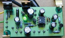
I have finished the positive regulator using the kit I got from ALW. I made few changes that seemed good ideas in theory, but I have not done listening test to compare with the stock version of the regulator. I cut the trace to the op amp supply pin and added a series 10 ohm resistor before the 10uF Oscon decoupling cap. This was to not have two high Q caps in parallel and to decouple the op amp from the bootstrapped supply at high frequencies where the op am has very low PSRR. The increased impedance for the op amps supply is not an issue since the driver between the output BJT and the op amp is a low capacitance mosfet. The mosfet is a very high impedance for the op amp to drive at audio frequencies and should not wiggle it's supply despite the 10 ohm resistance. The higher gate to source voltage of the mosfet allows the use of a LED, with it's much lower noise, for the level shifting. A correctly RC bypassed LM329 might be an even better choice. The current source and pass transistors are 100 MHz Toshiba BJTs and the regulator appears to be very stable. I would use a Hitachi C1775 and A872 for the current sources if I had some on hand. I replaced the 10K resistor bias for the current source LED with a jfet current source. This should result in about a 45dB improvement in LED voltage change with respect to input voltage change. Replacing the 10K with two 5K resistors with a cap to ground might be an even better approach. The feedback and voltage reference filter resistors have been greatly increased in value to allow the use of F-Dyne polypropylene and foil caps. Lead free 4% silver solder was used for the whole board. Will probably try a pre-regulator later on.
Andy did a fantastic job on the PCBs and I look forward to finishing them and listening to them this week. I hope he and Walt both, will forgive me for messing with an already excellent design, but it seems to be a rather incurable habit of mine at this point.
Fred
No, I will not answer questions about this on the forum, Mr. Pand S. I might discuss the rational for the changes via Email to interested individuals, but really don't want to get in that level of detail on the forum.
Attachments
Fred,
nice work. I would have been surprised if you had not tweaked
it.
Anyway, on a first brief read-through I think you argue well
for the reasons for your tweaks, and I am not so sure any
further clarification should be necessary.
It looks very professinoal, by the way, but then, you are
a professional.
Very good Fred, thanks for the description of what you did.
As X-ster says you description seems fairly complete.
If your purpose was not to provide help to peranders you might have failed.
At this point anyone that can't understand what you said shouldn't be messing with the circuit in the first place.
If it's not too much trouble let us know your sonic impressions.
A picture may not not beat a thousand words
"At this point anyone that can't understand what you said shouldn't be messing with the circuit in the first place."
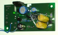
I was joking about refusing to help anyone. But as you point out, changes of this nature require an intimate knowledge of the circuit. I really don't think most people should make changes this extensive. Despite the description, there are about a half a dozen questions one should be asking before attempting these mods. There is more to this than I have described, and I would not attempt this on the basis of only what I have written, it is insufficient information. I do think I add the LM329 level shifting circuit but it will require a little Spice modeling to do correctly.
As you can see Andy's stock version is much nicer looking than my modified version and is shown with the DIP op amp package option.
"At this point anyone that can't understand what you said shouldn't be messing with the circuit in the first place."
I was joking about refusing to help anyone. But as you point out, changes of this nature require an intimate knowledge of the circuit. I really don't think most people should make changes this extensive. Despite the description, there are about a half a dozen questions one should be asking before attempting these mods. There is more to this than I have described, and I would not attempt this on the basis of only what I have written, it is insufficient information. I do think I add the LM329 level shifting circuit but it will require a little Spice modeling to do correctly.
As you can see Andy's stock version is much nicer looking than my modified version and is shown with the DIP op amp package option.
Attachments

Mods to ALW's Jung reg
Fred,
On the replacement of the LED current source with a JFET current source, I second that idea. I tried it out some time ago and it did improve the line rejection by a factor of more than 10. I also had trouble the right JFET CS, I settled for a 6mA one, most others I found were lower current, and with high loads the pass transistor ran out of base current (was a D44H11 I believe). But it also ruins your dropout voltage, which of course may not be an issue if you have enough input DC at hand.
Jan Didden
- Status
- This old topic is closed. If you want to reopen this topic, contact a moderator using the "Report Post" button.
- Home
- Amplifiers
- Power Supplies
- Super Regulator, collecting the facts