Empirically, throwing a big old crummy cap into these situations often greatly improves stability. In an EDN article, Bob Pease looked at this situation in a daisy chain of ICs, each locally bypassed with a ceramic, taking into account the inductance of the daisy chain; his recommendation, if I remember right, was to stick a tantalum cap on about every fifth chip.
Sy,
Indeed. Damping ringing etc can only occur if you can take energy away from the system. Very high quality caps with little or no loss factor can't do that, you just shuttle the energy around to other circuit parts. Once in a while you need a lossy component to actually dissipate that unwanted energy. An electrolytic with a couple of Ohms ESR works wonders sometimes.
Jan Didden
millwood said:andy, what will do if you parrellel one of those kemet caps with a big filter cap, like 3300uf, 40mohm esr, and 2nh esl? what would the magnitude and phase plots look like?
I don't think those numbers are realistic for a 3300uF cap. It's hard to find good cap data, but I did find data on the Rubycon web site for a 100 uF cap similar to what ALW uses in his super reg. In the voltage rating I was looking at (which happened to be 160V), the series resistance was about 0.25 Ohm, and the series resonant frequency was about 100 kHz, which comes out to be about 25 nH series inductance. Cornell-Dubilier has an applet which gives capacitor parameters for their big cans, but I haven't looked at the data.
The problem with very low ESR is this. At the series resonant frequency of the cap you get a pure resistance Resr. If we assume a resistive output impedance Rout of the emitter follower, then the loop gain will be attenuated by -20 log(Resr/(Resr+Rout)) dB at the series resonant frequency of the cap. If this attenuation is more than the value of the loop gain without the cap at the frequency of the series resonance of the cap, the notch from the series resonance will force the magnitude of the loop gain to be equal to one (0 dB) at a frequency somewhat less than the series resonant frequency of the cap. But at a frequency less than series resonance, there can be considerable phase lag from the cap, 50 degrees in our example. This can and will destabilize the circuit. Even if it doesn't oscillate, it will ring with transients of load current.
But as the ESR increases, the depth of the notch decreases and the notch becomes much wider. If you only get, say, 8 or 9 dB of attenuation at resonance, this may be enough to prevent the magnitude of the loop gain from crossing over 0 dB at or below resonance, and this is a good thing. Then it won't be until well after the cap becomes inductive that the loop gain crosses over 0 dB. This can be very good, since the inductance of the cap can actually contribute some phase lead to the loop gain right where the op-amp phase is getting a little squirrely. But if you've got a low ESR, you can't make it any bigger by putting other caps in parallel with it.
I liked Fred's earlier idea of an ultra-low ESR cap with a small series resistor of a few tenths of an Ohm. This way you know what your ESR is very accurately and can design your circuit for stabllity with that specific value in mind. I don't know of any ultra low ESR high-voltage caps (160V) which is what I would need in my power amp super reg.
The geometrical size of the cap has a lot to do with it resonance and ESR performance at a particular frequency. Most electrolytic caps turn into inductors at high frequencies so their very poor for knocking down HF noise, which makes them bad bypass caps. While it may be possible to make a circuit oscillate with a low ESR cap the value of the cap or it’s size in farads most certainly in most cases damped this effect again depending on the geometrical size. However, when using electrolytic caps out side their frequencies capacitance range it is possible to have surprises.
Most of the low ESR caps I have use are tantalums these are used to remove noise from switching supplies and digital circuits. Of course tantalum like electrolytic have their range over frequencies that they operate at and it is related to geometrical size of the caps. Even small value electrolytic and tantalums do not do well pass 5 to 10 MHz.
Anyway, for these type of bypass to be effective at higher frequencies they should be bypassed with a ceramic caps if the noise spectrum is broad and with HF energy
Hi Jim,
Just to clarify, my two previous posts were referring to loading the output of the super reg (where it affects stability in a very direct way) rather than supply bypassing. Some of the other posts ended up discussing bypassing, which is a somewhat different, though also important issue. I was mainly trying to bring up the dangers of loading the output of a super reg with a low ESR capacitor. Especially when using op amps with 100 MHz gain bandwidth product like the AD797.
In the case of the super reg, the electrolytic load cap is actually part of the frequency compensation of the circuit itself. Just wanted to reiterate that I wasn't referring to bypassing, where often a low ESR solution is quite appropriate.
Andy,
Well I added a 68uf low ESR tantalum in parallel with the 47uf that in the circuit and no oscillation. Its’ time like this it would be nice to have that 10u volt per division amplifier that Tektronix use to make for their 7000 series scopes. I only tried this on the negative supply where he opamp runs in inverted.
")
Well I added a 68uf low ESR tantalum in parallel with the 47uf that in the circuit and no oscillation. Its’ time like this it would be nice to have that 10u volt per division amplifier that Tektronix use to make for their 7000 series scopes. I only tried this on the negative supply where he opamp runs in inverted.
andy_c said:[snip]The problem with very low ESR is this. At the series resonant frequency of the cap you get a pure resistance Resr. If we assume a resistive output impedance Rout of the emitter follower, then the loop gain will be attenuated by -20 log(Resr/(Resr+Rout)) dB at the series resonant frequency of the cap. If this attenuation is more than the value of the loop gain without the cap at the frequency of the series resonance of the cap, the notch from the series resonance will force the magnitude of the loop gain to be equal to one (0 dB) at a frequency somewhat less than the series resonant frequency of the cap. But at a frequency less than series resonance, there can be considerable phase lag from the cap, 50 degrees in our example. This can and will destabilize the circuit. Even if it doesn't oscillate, it will ring with transients of load current.
But as the ESR increases, the depth of the notch decreases and the notch becomes much wider. If you only get, say, 8 or 9 dB of attenuation at resonance, this may be enough to prevent the magnitude of the loop gain from crossing over 0 dB at or below resonance, and this is a good thing. Then it won't be until well after the cap becomes inductive that the loop gain crosses over 0 dB. This can be very good, since the inductance of the cap can actually contribute some phase lead to the loop gain right where the op-amp phase is getting a little squirrely. But if you've got a low ESR, you can't make it any bigger by putting other caps in parallel with it.
I liked Fred's earlier idea of an ultra-low ESR cap with a small series resistor of a few tenths of an Ohm. This way you know what your ESR is very accurately and can design your circuit for stabllity with that specific value in mind. I don't know of any ultra low ESR high-voltage caps (160V) which is what I would need in my power amp super reg.
Andy,
Thanks for that, very logical. There's one thing that isn't clear to me though. Using more esr prevents the loop gain to go down to 0dB at the point when there is considerable phase lag. That means there WILL be excess loop gain at that point. Wouldn't that make the ringing worse, rather then less?
Jan Didden
that would be the 7A22jewilson said:Andy,
Well I added a 68uf low ESR tantalum in parallel with the 47uf that in the circuit and no oscillation. Its’ time like this it would be nice to have that 10u volt per division amplifier that Tektronix use to make for their 7000 series scopes. I only tried this on the negative supply where he opamp runs in inverted.
It's the 5A22N for the 5XXX series.
jack
andy_c said:I don't think those numbers are realistic for a 3300uF cap.
the esr figures come from a couple of datasheets I have seen, and are in line with impedance figures at BC Components.
ESL is highly dependent on layout, and some measured figures I have seen vary from 400ph to 4-5nh.
millwood said:
ESL is highly dependent on layout, and some measured figures I have seen vary from 400ph to 4-5nh.
For 3300 uF ESL will depend largely on the shape and size of the capacitor, regardless of PCB layout. For such a bulky elcap 20-50 nH seems more realistic.
janneman said:(...)There's one thing that isn't clear to me though. Using more esr prevents the loop gain to go down to 0dB at the point when there is considerable phase lag. That means there WILL be excess loop gain at that point. Wouldn't that make the ringing worse, rather then less?
Hi Jan,
Good question. Sorry for the delay, but I can only post after about 7:30 PM California time after getting home from work. Anyway, if you look at the transfer function from the non-inverting input voltage Vin to the output voltage Vout,
Vout/Vin = A/(1 + AB)
Where A and B are open loop gain and feedback factor respectively. The stability/ringing issue is really a divide by zero problem in the above expression. If we oversimplify a bit and assume the phase of AB is -180 degrees, a worst-case value, then AB is just real and negative instead of complex. If |AB| is 1, then we have a divide by zero problem, an oscillator. If |AB| is near 1, then we have marginal stability and ringing, possibly even a growing oscillation if |AB| is just a bit larger than 1. Paradoxically, if |AB| >> 1, we're out of hot water again. Suppose |AB| is 100 and the phase is -180 degrees. Then the denominator of the above expression is -99, which is well away from zero. So we're actually more stable in this case than if the loop gain were less.
This can have weird practical consequences. Those funky two-pole compensation circuits for power amps have this property. There's a 40 dB/decade rolloff initially, which transitions to a 20 dB/decade rolloff before the unity loop gain frequency is reached (because of the presence of a zero). Suppose you could put an attenuator in the open loop gain that reduced the gain without affecting the phase. If you reduced the gain enough, it could become unstable or marginally stable again because the loop gain could be made to be near unity where the phase lag was large. Same kind of situation.
jewilson said:Well I added a 68uf low ESR tantalum in parallel with the 47uf that in the circuit and no oscillation. Its’ time like this it would be nice to have that 10u volt per division amplifier that Tektronix use to make for their 7000 series scopes. I only tried this on the negative supply where he opamp runs in inverted.
Is this a super reg topology? Anyway, you really had me stumped there. I'm not real familiar with the properties of tantalum caps, since my own searching was for a high-voltage regulator where I needed 160V units. Anyway, I dug up this 1998 article from EDN here http://www.reed-electronics.com/ednmag/archives/1998/102298/22ms402.htm. I've attached a picture from it. I haven't been able to find impedance plots for any 47 uF tantalums though. But judging by the plots below, the tantalum caps aren't low ESR at all. In fact they look like a really excellent broadband resistive impedance, just perfect for this application. The plot of the ceramic looks almost exactly like the Kemet pic.
Attachments
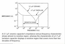
Ahh, nice picture! So it looks like the unity loop gain frequency will now be above the series resonant frequency of the cap in the 47 uF case - which will give a stable circuit. Thinking about it some more, the "low ESR = bad" is really an oversimplification. The lower the series resonant frequency of the cap, the lower the ESR you can get away with.
Thanks for posting that. I couldn't find the graphs on the Cornell-Dubilier web site.
Thanks for posting that. I couldn't find the graphs on the Cornell-Dubilier web site.
Everything you want to know about regulators but were afraid to ask
"Ahh, nice picture! So it looks like the unity loop gain frequency will now be above the series resonant frequency of the cap in the 47 uF case - which will give a stable circuit. Thinking about it some more, the "low ESR = bad" is really an oversimplification. The lower the series resonant frequency of the cap, the lower the ESR you can get away with."
I don't know if this is really true in most cases. Part of having a cap on the output is that the open loop gain starts drop as the cap impedance approaches to open loop output impedance of the regulator. A regulator that does not have enough phase margin to be stable without the output cap can often be made stable due to this. The original Sulzer article made note of this and the ability to use an uncompensated op amp to get more feedback and lower output impedance. He used an uncompensated NE 5534. A cap with a resonant frequency low enough that the inductive (rising with frequency) part of the output impedance has reached a high enough magnitude were it doesn't swap the open loop output impedance at the point the regulator is at unity gain, could be unstable. Sulzer did a much better job of explaining it. Anyone who wants really understand this type regulator should read:
A High Quality Power Supply Regulator for Operational Amplifier Preamplifier
M. Sulzer TAA 2/1980
As I told AWL, I feel this is the Rosetta Stone for audio power supply regulator design. Andy also liked the article very much when I made him aware of it. This was the first many articles on op amp based supplies in TTA but I still reread from time to time for it's excellent over view on the subject.
A High Quality Power Supply Regulator for Operational Amplifier Preamplifier
M. Sulzer TAA 2/1980
Regulators Revisited
M .Sulzer TAA 1/1981
Measuring Power Supply Output Impedance Part I
J. Breakall TAA 1/1983
Measuring Power Supply Output Impedance Part II
J. Breakall TAA 2/1983
Power Up
R. Marsh TAA 3/1983
A Wideband Power Supply
J. Didden TAA 1/87
Regulators For High-Performance Audio Part 1
W. Jung. TAA 1/95
Regulators For High-Performance Audio Part 2
W. Jung TAA 2/95
Regulators For High-Performance Audio Part 3
J. Didden TAA 3/95
Improved Positive/Negative Regulators
W. Jung Audio Electronics 4/00
Re: Everything you want to know about regulators but were afraid to ask
Fred,
I might add:
www.onsemi.com/pub/Collateral/SR003AN-D.PDF
Fred,
I might add:
www.onsemi.com/pub/Collateral/SR003AN-D.PDF
- Status
- This old topic is closed. If you want to reopen this topic, contact a moderator using the "Report Post" button.
- Home
- Amplifiers
- Power Supplies
- Super Regulator, collecting the facts