Hi,
Another question:
Set aside the excellent low quiescent current and dropout voltage of the LT3080, I saw one difference between it and the LM317 is that the 3080 uses a 10uA CCS as reference instead of 1.25V as in the 317. Is this the reason why you have R7 (100k) to develope quiescent current through the group R4/R5/R6?
If I use LM317 or other similar ICs (LT1086, LT11963...) instead, then we dont need this R7 and we come back to the original Maida circuit, except the mosfet vs. bjt? Or if we still keep R7 then we'll need to recalculate as the voltage across R4/R5/R6 will be (1.25V + Iadj*R7)?
Sorry but these kept bugging me while I'm trying to understand your circuit and build my version using the parts that can be found around here.
Thanks,
Duong
If you want to build a regular Maida Regulator, have a look at Mike Maida's original Linear Brief #47. For a negative regulator, reverse the diodes, use PNPs instead of NPNs, and use an LM337 instead of the LM317. You can see an example here: http://www.diyaudio.com/forums/tube...-engineers-approach-300b-set.html#post2361302
To work properly, the original Maida regulator needs at least 10 mA of current running through it at all times otherwise it won't regulate properly. This current generally runs through the feedback network. At high output voltages, this results in huge amounts of power dissipated in the feedback network. Furthermore, using more modern parts it is possible to improve the line rejection (ripple rejection) by 50-ish dB. The output impedance is improved considerably as well. That's why I developed the 21st Century Maida Regulator.
You can use an LT1086 but it requires the same quiescent current as the LM317, hence, provides no advantage.
The LT1963 is not a floating regulator. It requires a connection to ground. It won't work in a Maida Regulator for this reason.
The LT3080 is the only modern IC I have been able to find that meets the requirements:
1) Floating regulator (i.e. no ground reference needed for the IC itself).
2) Low worst case quiescent current.
~Tom
Set aside the excellent low quiescent current and dropout voltage of the LT3080, I saw one difference between it and the LM317 is that the 3080 uses a 10uA CCS as reference instead of 1.25V as in the 317. Is this the reason why you have R7 (100k) to develope quiescent current through the group R4/R5/R6?
My 21st Century Maida Regulator works as follows:
- Iref = 10 uA flows through R7 (100 kohm) setting up a reference voltage, Vref, of 1.00 V.
- The IC will control the output voltage such that the voltage across R5||(R4+R6) is equal to Vref.
- This sets up a current of Vref/(R5||(R4+R6)) in R9, resulting in an output voltage of Vout = R9*Vref/(R5||(R4+R6)).
~Tom
Thanks, this is exactly what I assumed.
I finally had some time to test the LM317 version of your circuit, here under is my initial report.
1. At first, I kept using R7 = 100k & C3 = 10uF to have soft start. Due to this, Vref across R456 became ~7.5VDC (Iadj of my LM317 is ~60uA). Hence R456 was chosen 680R to keep quiescent current above 10mA, R9 was 24k/10W to have Vout approx. 280V.
With input supplied from my Kikusui bench PSU (310-350VDC regulated), the circuit worked as calculated, delivered Vout ~282VDC.
However:
- The soft start wasnt perfect: after turn on, Vout started at ~130VDC and increased quite fast to ~275VDC after 2-3 seconds. The last few volts are reached after ~10s and the circuit took some more time to achieve stablized value. I actually expected the soft start to have more gradual/linear output voltage growth.
- Vout (loaded and unloaded) wasnt very steady, still varied around 0.2-0.3VDC in static condition (regulated input voltage, no change in load)
- Difference in output between loaded & unloaded: with the circuit running, when a 3.9k/50W load was connected to output I could see an INCREASE of about 0.5V and keep gradually climbing to a finalized value of approx. 1VDC. When the load was disconnected, the circuit took a few minutes to gradually come back to initial unloaded value.
2. With this strange behavior, I suspected the Vref wasnt stable and it made the changes in Vout. My measurements approved this: Vref can change 0.01-0.03V in varied situations. So I guessed maybe Iadj of LM317 is not very stable (unlike constant 10uA as in LT3080), only the Vref 1.25V can be kept constant.
3. I decided to removed (shorted) R7/C3, this will make Vref across R456 steady 1.25V. R456 was also changed to 100R, to keep quiescent current above 10mA.
With these change, I no longer had soft start, but the variations in output were reduced significantly: only about 0.1V in static conditions and 0.1-0.2V between loaded/unloaded.
So, looks like I still have to go for LT3080 if better performace is required
However, Tom, do you meet these problems (non-linear soft start, variations in output voltage) with your circuit? Any suggestion to improve?
Thanks,
Duong
The LM317 is not a replacement for the LT3080. As you have discovered, my 21st Century Maida Regulator will not work if you use the LM317.
The LM317 works by maintaining 1.25 V from ADJ to OUT. The LT3080 works by sourcing 10 uA through an external resistor. The voltage on the SET pin is buffered to the OUT pin. The 10 uA SET current makes in real easy to implement a soft start. This feature is not available on Mike Maida's original regulator.
If you require soft start, want the best performance, and would like to use reasonably sized power resistors (rather than the 10+ W types needed for the original Maida Regulator at higher output voltages), I suggest you build my 21st Century Maida Regulator. You can also design your own regulator. I did that for a while until I landed at the 21st Century Maida Regulator and was happy with the performance.
If you're not comfortable soldering the SMD components (they are actually pretty big by SMD standards), I do offer boards with the SMD components populated.
~Tom
However, Tom, do you meet these problems (non-linear soft start, variations in output voltage) with your circuit?
I have not encountered any of these issues with my circuit. On start-up, the output voltage rises smoothly without overshoot. When a 200 mA load is applied, the voltage droops, maybe, 10 mV. I'm only able to measure this on my 6.5 digit bench top DMM. My handheld Fluke 73 doesn't notice...
If you would like to build the 21st Century Maida Regulator, I'll be glad to help. If you wish to continue to debug your own design or design something from scratch, you'll probably find a bigger audience and better help if you start a new thread and put a schematic in your first post.
Thanks,
~Tom
I actually have the need for a decent regulator, hence I'm truly interested in your circuit.
Since it's really not easy/economic for me to order your boards (sorry), and I cannot find the LT3080 around here either, I guess the best choice is to build with what my hands can reach and start from your excellent ideas.
It might takes me quite some times to reach the same conclusions as yours, but by trying them myself, I will have better understanding and maybe other solutions later. If then, you'll be the first one I'd ask for opinions.
Thanks for your time and suggestions.
Duong,
Fair enough.
You can try my HV Regulator 3.2. I no longer support the circuit, but you can build it from parts you can find locally. You may find some useful information in this thread as well.
~Tom
You can try my HV Regulator 3.2. I no longer support the circuit, but you can build it from parts you can find locally. You may find some useful information in this thread as well.
~Tom
Tom, I've been studying your regulator, and I have a question: Why a 20V rating for the TVS protecting the LT3080?
The MOSFET gate is 10V above the LT's output, and very conservatively, its source must be at least 4V below that for it to conduct. I would think you'd spec a TVS that does not conduct below 6V but starts to conduct above that point. That way, you'd provide the maximum possible protection to the LT.
I'd appreciate your thoughts.
CPaul:
The LT3080 is rated for 40 V (ABS MAX) and the currently specified TVS diode keeps it below 20-something, so all should be good.
However, as you said, better protection could be had if the voltage of the TVS diode was lowered. That's actually a good point. Thanks for bringing it up.
The TVS diode is included as I wanted some additional protection for the LT3080 beyond what the cascode (Q1 + zener) provides. This to guard against transients caused by loose connections in tube sockets and the like. Even if you can go as low as 6 V for the TVS diode, I would probably leave a fair amount of margin there. You don't want the TVS diode to turn on at every voltage transient - leave those for the regulator to control. But you do want it to be effective in protecting the IC if needed.
So the choice is between protecting the IC and not participating in the circuit during normal operation - as is the case for any protection circuit. I chose 20 V to err on the "not participating" side during prototyping. It worked well, so I didn't think to revisit it. But for a Rev. 2.0, I think it makes sense to pull it in a bit. 10 V should be a safe value as well. That would leave about 4 V of margin.
It does have to be a TVS diode, though. A regular zener will just go 'poof' if it ever gets to conduct in that spot.
~Tom
@tomchr
I've got an initial need for two adjustable high voltage regulators for a tube tester.
Since I cannot work with chemicals anymore and have limited movement in my hands I ordered two PCB's from evilBay. Before I order parts to populate I would highly appreciate your input on what / how I can improve while keeping costs down.
The original brief of the Maida regulator mentioned something like 180V at 25mA max and I like to go higher with the voltage and current,. The seller mentioned it will go to 285V but don't know if it is capable of delivering a higher current.
For the tubes I like to test up to KT66,/ EL34 and will need in the order of 120mA. I do not want to go above 300V, if it turns out I cannot go above 275V then I am OK with that too. (plus the pre amp tubes but those current draws are not the problem).
I've been thinking about replacing the TIP50 with the E13005, what are your thoughts? Another alternative is using a darlington or mosfet but then I'll start to get into trouble with the layout.
I am aware of the dissipation issues but will address that with a tapped transformer.
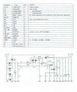
I am attaching the diagram and parts list.
I've got an initial need for two adjustable high voltage regulators for a tube tester.
Since I cannot work with chemicals anymore and have limited movement in my hands I ordered two PCB's from evilBay. Before I order parts to populate I would highly appreciate your input on what / how I can improve while keeping costs down.
The original brief of the Maida regulator mentioned something like 180V at 25mA max and I like to go higher with the voltage and current,. The seller mentioned it will go to 285V but don't know if it is capable of delivering a higher current.
For the tubes I like to test up to KT66,/ EL34 and will need in the order of 120mA. I do not want to go above 300V, if it turns out I cannot go above 275V then I am OK with that too. (plus the pre amp tubes but those current draws are not the problem).
I've been thinking about replacing the TIP50 with the E13005, what are your thoughts? Another alternative is using a darlington or mosfet but then I'll start to get into trouble with the layout.
I am aware of the dissipation issues but will address that with a tapped transformer.
I am attaching the diagram and parts list.
Attachments
Last edited:
Yeah... That's not my circuit. I can probably help you figure it out, but I think that would be best served in a separate thread. You'd attract more help from others that way as well.
I generally suggest to build things according to the assembly manual and verify operation before modifying it. Or at the very least set it up in a circuit simulator and play with it there.
~Tom
I generally suggest to build things according to the assembly manual and verify operation before modifying it. Or at the very least set it up in a circuit simulator and play with it there.
~Tom
Tom,
I ordered and built your circuit, with almost all the parts you suggested, minor changes to capacitor sizes due to stock issues at Digikey. I've been having problems with test results however.
I'm testing with a 20K resistive load at the output (to keep power down), and applying a DC voltage from a 350V power supply at the input. That's as large as we have in the lab, though I intend to operate at 420V eventually, when my transformer arrives.
I am unable to change the output voltage at all, by changing the trim pot. I removed the trim pot and tried different resistors and still so no change even in the 10's of mvolts.
R3 is 8.2 Ohms, R9 is 200K.
I am getting a Vout that is approx 5 volts below Vin, but drops as Vin is increased to 350V to 9volts below Vin.
Any ideas on where to check, or suggestions to probe for known voltages, so that it's working as intended.
Thanks,
Scott
The input voltage should always be at least 15 V above the output voltage. So at the lowest point of the input ripple, the input voltage should be at least Vout + 15 V.
In your case, you are applying 350 V on the input and expecting 400 V on the output (R9 = 200 kΩ), so about 355 V out and no regulation sounds about right.
Either increase the input voltage or decrease R9 (to get lower output voltage). For example, if you were to solder a 470 kΩ resistor in parallel with R9, you would get about 280 V out.
The polypropylene capacitors around the regulator are critical. In particular, the 2.2 uF on the output needs to be at least 2.2 uF for stability. So be careful with substitutions.
~Tom
Ok,
I think I understand. Can you verify?
The DC in becomes the relative ground for the regulator, and the trim pot can adjust the voltage that is riding above the DC out of the resevoir capacitor, but the only way to lower the voltage below the DC in across R9 which is from the set voltage to ground?
Sorry I'm not a power supply guy by any means,
Thanks,
Scott
Both the input voltage and the output voltage are referenced to ground. The regulator forces 2 mA through R9 and this sets up the output voltage from ground to +Vout of 2*R9 (R9 in kΩ).
What I think may cause some interference in your mind is that both the LT3080 and LM317 are floating regulators. This means the regulator IC itself does not know where ground is. In case of the LT3080, the IC supplies a precision current out the IREF pin and drives the OUT pin to the same potential as the IREF pin.
~Tom
Tom,
I managed to get some LT3080 for testing and the result was a big improvement in comparison to original Maida circuit.
By the way, I just had an idea of using tubes instead of Mosfet as cascode device, but I'm still not really sure how to do it, do you have any suggestion?
Thanks,
Duong
I managed to get some LT3080 for testing and the result was a big improvement in comparison to original Maida circuit.
By the way, I just had an idea of using tubes instead of Mosfet as cascode device, but I'm still not really sure how to do it, do you have any suggestion?
Thanks,
Duong
Using a tube as the cascode device. That's a pretty interesting idea. If the tube can handle the power dissipation, you should be able to use a circuit to mine. Just increase the zener voltage on D2 such that you end up with at least 1.6 V across the regulator IC under all operating conditions (excluding the over-current condition, obviously) and you should be fine.
Test the transient response of the circuit, though. The output impedance of a tube cascode (cathode follower) is relatively high compared to that of a MOSFET follower, which may affect stability of the regulator IC.
~Tom
Test the transient response of the circuit, though. The output impedance of a tube cascode (cathode follower) is relatively high compared to that of a MOSFET follower, which may affect stability of the regulator IC.
~Tom
Thanks for your tips, I will keep them in mind.
Embarrassingly I'm not familiar with how the transient response is tested, so further explanation is really appreciated.
Anyway I will try this idea when freetime arrives, the tube might be Russian 6S19P (6С19П) or 6AS7...
Thanks,
Duong
Embarrassingly I'm not familiar with how the transient response is tested, so further explanation is really appreciated.
Anyway I will try this idea when freetime arrives, the tube might be Russian 6S19P (6С19П) or 6AS7...
Thanks,
Duong
- Home
- Vendor's Bazaar
- 21st Century Maida Regulator