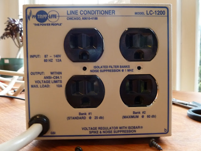
I just picked up an older Tripp Lite LC1200 line conditioner with the hopes of getting it to work. The problem: NO OUTPUT. The switch light turns on and I've metered 120 to the board to determine the circuit breaker and switch are working properly. I've also looked for any obvious component damage but couldn't find any budging/leaking caps, toasted resistors, or any thermal damage. That's about where my knowledge ends. I need some direction as to what to troubleshoot next and if it's not straight forward how to do it.
I only got him for $5 so as long as it cost me about $25 or less to fix I'm winning.
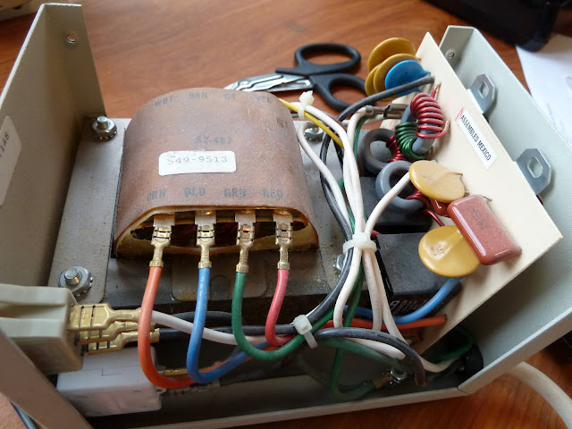
Here's some photos of the inside:
I only got him for $5 so as long as it cost me about $25 or less to fix I'm winning.
Here's some photos of the inside:
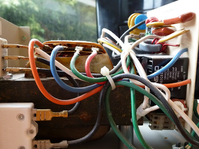
Hmmm. What voltage should I be able to see across the transformer? Across the top I have White Brown CT(?) Yellow, then across the bottom I have Orange Blue Green Red. What should I be looking for?
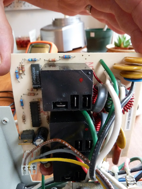
Also I was thinking it might be the MOV, but there's no obvious sign of damage there.
Also I was thinking it might be the MOV, but there's no obvious sign of damage there.
Identify the primary leads (input) of the xfmr, and the secondary leads (output). You should be able to determine this by recognizing the secondary feeds the receptacle, and the primary comes from the relay PCB. Determine if there is any primary excitation. If there is, but no secondary output, the xfmr is fried (unlikely). If there is no primary excitation, it's not getting through the PCB, and you have to identify why.
I used to have a line conditioner / balanced isolation transformer of a different brand (the name begins with an F and was sort of expensive).
It got fried (along with a some of my other gear) when lightning hit nearby. I got the schematic for it and found that all of the surge clamping devices and line filtering devices were on the secondary of the balanced transformer so were never in the circuit if it was off. The unit had a controller circuit with a soft start and a relay. It also had a line voltage meter on the primary. Those circuits were energized all of the time and had nothing to protect them. Not even a power transformer since the supply for the controller was derived directly from the 120V line. I fixed the thing but couldn't stand to keep it knowing what a terrible design it was. I would have needed a power conditioner to protect it! It is an example of a good idea with a Terrible implementation. It can't even save it's own circuits!
It got fried (along with a some of my other gear) when lightning hit nearby. I got the schematic for it and found that all of the surge clamping devices and line filtering devices were on the secondary of the balanced transformer so were never in the circuit if it was off. The unit had a controller circuit with a soft start and a relay. It also had a line voltage meter on the primary. Those circuits were energized all of the time and had nothing to protect them. Not even a power transformer since the supply for the controller was derived directly from the 120V line. I fixed the thing but couldn't stand to keep it knowing what a terrible design it was. I would have needed a power conditioner to protect it! It is an example of a good idea with a Terrible implementation. It can't even save it's own circuits!
- Status
- This old topic is closed. If you want to reopen this topic, contact a moderator using the "Report Post" button.
- Home
- Amplifiers
- Power Supplies
- What can go wrong with a power conditoner?