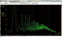
This the spectrum I get for my household 120V 60hz AC line. I measured this by just dropping the voltage down to line level (~2V) using a simple resistor voltage divider and recording it with my soundcard at 96Khz/24bit.
Pretty strong and extended odd order harmonics and a fair amount of even order as well.
Is this normal ? Is this what typical household ac looks like ? Frankly I wasn't expecting this, I was pretty taken aback but has anyone measured the spectrum on their ac line ? I am very curious how does it look for others.
Attachments
Correct, an AC filter is designed to block/suppress RF frequencies, but will do nothing to the harmonics between 60 and 20k. As far as whether or not those harmonics matter depends on the application.
When I AC heat DHT's, I prefer to run my heater source through a ferroresonant transformer, which produces harmonics only out to about the 11th. Higher order trash is eliminated. So you get slightly cleaner and regulated power. But for converting AC to DC for amplifier power supplies, this source at your house panel is just fine. Having a cleaner sine wave won't really improve the situation. In fact, it is the use of rectifying power supplies in your home and on the grid that causes the voltage to look like this in the first place.
Any attempt to clean up the source harmonics will normally result in higher source impedance as seen by your amps, which is usually not the goal.
simon, actually those are indeed 60hz harmonics. What you see 1Khz is actually the 17th harmonic (1020hz). I will try to just attach the wav file so that anyone can look at it directly.
zigzagflux,
if this doesn't matter when converting ac to dc, then why does the higher frequency interference (emi/rfi) matter and is usually desired to be filtered out ?
zigzagflux,
if this doesn't matter when converting ac to dc, then why does the higher frequency interference (emi/rfi) matter and is usually desired to be filtered out ?
if this doesn't matter when converting ac to dc, then why does the higher frequency interference (emi/rfi) matter and is usually desired to be filtered out ?
Not sure why we are discussing emi/rfi at all in this specific case; you have not shown RF to be an issue on your supply. All you have is a typical distribution of harmonics due to rectifying loads.
These harmonics can be easily filtered out by a power supply filter (series inductors and parallel capacitors). So they are not detrimental to the performance of a power supply. In fact, a square wave AC input rectifies very nicely, with low peak currents (improved crest factor).
While the inductance equation XL=2pifL implies RF will be greatly attenuated at the series choke, the reverse is true. RF can fly right through an inductor's stray winding capacitance. Similarly, RF will not see a parallel capacitor as a short circuit (1/(2pifC)), rather it will see the lead inductance as significant. So RF is not attenuated by a power supply filter like the lower order 60Hz harmonics are. Once you have RF inside your power supply, tubes or transistors are happy to amplify or oscillate in response to their presence. Bad news.
So maybe a question for you to keep the thread on course- why are you concerned about the typical FFT spectrum of your AC line?
well it was just an extension of thought stemming from general concern about power line quality. Obviously the soundcard can't measure past that so its unknown at this point but I suppose it wouldn't be entirely unfair to assume the precence of RF either by conduction or radiation.Not sure why we are discussing emi/rfi at all in this specific case; you have not shown RF to be an issue on your supply. All you have is a typical distribution of harmonics due to rectifying loads.
A possible explanation like this is perhaps what I was looking for. Let me process that information a little bit more although at first instance I think that arn't the X and Y type caps in a typical emi/rfi filter parallel as well ? Perhaps they are quite small in value to matter in this way.While the inductance equation XL=2pifL implies RF will be greatly attenuated at the series choke, the reverse is true. RF can fly right through an inductor's stray winding capacitance. Similarly, RF will not see a parallel capacitor as a short circuit (1/(2pifC)), rather it will see the lead inductance as significant. So RF is not attenuated by a power supply filter like the lower order 60Hz harmonics are. Once you have RF inside your power supply, tubes or transistors are happy to amplify or oscillate in response to their presence. Bad news.
So maybe a question for you to keep the thread on course- why are you concerned about the typical FFT spectrum of your AC line?
well at the time when I started the thread I wasn't even sure if I should be concerned or not. just educating myself.
simon, actually those are indeed 60hz harmonics. What you see 1Khz is actually the 17th harmonic (1020hz). I will try to just attach the wav file so that anyone can look at it directly.
zigzagflux,
if this doesn't matter when converting ac to dc, then why does the higher frequency interference (emi/rfi) matter and is usually desired to be filtered out ?
Why is the 17th harmonic so large? Not what is expected.
If you look through the Blowtorch II thread you can find some RF spectrum shots of different types of power supplies.
You should look up a bifilar choke. It will clean up most of what you see.
Depending on wgere you live and what industry or offices are near you, that looks about right for the mains. Worked on some gen set controllers that synced with the mains and we got false zero crossings up to the 13th harmonic in some places, so the EE's went away and palyed with some analoge circuitry and DSPs to solve the issue. Being near large HVAC installations is the worse scenarion.
Hi percy, sorry for my english, I helped with Google translator.
I find it very interesting, and above all very ingenious, way of measuring the noise in the mains. Please, can you give a full explanation, a little tutorial on how to do?
How does the resistive divider and as we connect? Between earth and live, between earth and neutral, between live and neutral, or use all three? How do you connect to the computer and programs can be used?
But what I find most interesting is if you could use to measure the noise in any part of an electronic device. For example, if the noise could be measured in the power supply of a amplifier, the power pins of the operationals, etc.
If it works maybe it could be used as a measuring device that shows the effects of changing components, add filtering, bypassing, change cables, different supports against vibration, etc.
Each of these changes may show changes in the spectrum of noise of each stage. Naturally, as the supplies are in DC, it would be necessary to put a capacitor in series, each capacitor would have a different frequency spectrum. But that's good, because would choose the more neutral capacitors and with better features to Audio. As the noise will have a much lower level than that of the mains may also be needed any amplification.
Perhaps you could do any of these tests and post them here. But this is just a suggestion, at least a small tutorial, please.
Happy days.
Hi Raul,
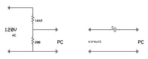
this is between Live and Neutral. Ground was not in the picture. I wired up a high and low value resistor in series (16.2k + 200ohm) and that 16.4k served as a load to the 120V outlet Live and Nuetral. Then I just tapped the ~1.5V drop across the 200ohm resistor and fed it into the Line-In input of my soundcard and used WaveSpectra to observe the spectrum real time. WaveSpectra also produced a wav file of the recording. That’s it. Essentially I have done nothing new than using the soundcard as a scope or analyzer. Other than perhaps a very dangerous way of hooking up the soundcard to the ac outlet!
Keep in mind this is limited by the soundcard’s bandwidth which typically is about 48khz, maybe 96khz with some pro-audio interfaces, so this is not quite useful for high(rf) frequencies which I suppose is what you would find on the ground wire and post-power-supply or other areas that you were referring to.
Last edited:
The resistive divider method can cause false readings if the neutral is dirty since the PC is typically connected to ground, and the divider connects the PC to the neutral causing a possible ground loop.
I found another method that is especially easy for tube guys. Fetch an output transformer, any OPT, SE or P-P good for 10 watts or more and at least 3 K ohms, preferably with good frequency response. Connect an 8 ohm load on the 4 or 8 ohm tap, or anyload you have that is close. You want the transformer loaded, but not overloaded. Solid state guys, use a power (mains) TOROID (not EI) with a secondary in the 6 volt range. Again, load it lightly. Connect the loaded secondary to your measuring equipment using a voltage divider as appropriate for a sound card, and....plug the primary right into the wall outlet!
A vacuum tube OPT typically sees several hundred volts of signal on its primary, 120 volts is nothing. A mains toroid usually (but not always) has a good high frequency response.
I used this method to measure my line quality several years ago and found it decent with about 3% distortion durnig light load times, and nearly 5% during dinner time on a hot summer evening. I made spectum plots with my sound card and didn't see anything worthy of remembering.
I have lived in this house for 34 years and the Florida lightning finally zapped the pole transformer in the backyard. The original transformer was about 3 1/2 feet tall and it took a fork lift to remove it. The replacement was about 2 1/2 feet tall and enclosed in a plastic housing. The same fork lift moved it but I could tell it was much lighter by the way the driver handled it.
Now If I repeat the same measurement using the SAME OPT and HP8903A audio analyzer I get 7% during light loads and I have seen readings over 10%. The waveform shows obvious signs of transformer saturation.
The plots showing high levels of higher order energy are probably locally polluted. I have found that HVAC units are not the prime offenders. The PC and flat screen TV's are!
- Status
- This old topic is closed. If you want to reopen this topic, contact a moderator using the "Report Post" button.
- Home
- Amplifiers
- Power Supplies
- Distortion in ac mains supply ?