I'm currently planning an amplifier, and it seems that I couldn't find a good transistor that have high enough Vce and other specs I wished, so I only have my BC550C/560C to use, which is lower Vce. As my rail voltage from my transformer after filtered and rectified, it is roughly 27V-28V, I need to lower it to something from 20V-22V to cope for BCs.
I'm current finding some method of reduce rail voltage (regulator ?) with minimum dissipation, without insane complexity & cost.
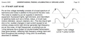
And method of protection against or able to withstood small overvoltage. (spike as attached description)
I'm also thinking incorporate some inductor, which will improve the PSRR and decrease some rail voltage ? what is the drawback of using inductor in power supply ?
I'm current finding some method of reduce rail voltage (regulator ?) with minimum dissipation, without insane complexity & cost.
And method of protection against or able to withstood small overvoltage. (spike as attached description)
I'm also thinking incorporate some inductor, which will improve the PSRR and decrease some rail voltage ? what is the drawback of using inductor in power supply ?
Attachments
Would you give me typical value of resistor ?
.
Search in any datasheet, the recommended minimum current in the zener under question. Add the load current to it. So, then knowing voltage drop in the resistor, calculate the resistor value and power loss in it. Finally, choose a smaller normal value resistor, and the power of such slowly greater than it. Example: supuose diode current 10mA, load current 50 ma and voltage drop 15V. Then, Ir = 10mA plus 50mA = 60mA.
R = 15V / .06A = 250ohms. Choose 220R.
P = 15V * .06A = .9W, choose 1W.
If the power is not so big, you can also think in a TL431 voltage regulator, that has lower output resistance. But calculus is a bit more complex.
Good luck.
just to ask, it is wise to only provide regulated supply to non- output stage (output stage using raw unregulated supply), like this I reduce the power (& dissipation) needed to pass through regulation unit. (output use tons of currents)
So here I have attached the link for the choice i would take, so i would like your suggestion on resistor I need :
http://malaysia.rs-online.com/web/p/zener/0812538/
its datasheet : http://docs-asia.electrocomponents.com/webdocs/0029/0900766b800297e6.pdf
Just to be sure, in my input stage, I have another pair zener is 15V from ground, I suppose it won't have problems ?
Through simulation, other than output, the amplfieronly consume 20mA maximum, giving extra 10mA = 30mA.
While output is using about 6A (OMG), I think last time because of that output it got worst PSRR
So here I have attached the link for the choice i would take, so i would like your suggestion on resistor I need :
http://malaysia.rs-online.com/web/p/zener/0812538/
its datasheet : http://docs-asia.electrocomponents.com/webdocs/0029/0900766b800297e6.pdf
Just to be sure, in my input stage, I have another pair zener is 15V from ground, I suppose it won't have problems ?
Last edited:
> I only have my BC550C/560C to use, which is lower Vce. As my rail voltage ... is roughly 27V-28V, I need to lower it to something from 20V-22V to cope for BCs.
BC550 is rated 50V.
http://www.nxp.com/documents/data_sheet/BC549_550.pdf page 2
> reduce rail voltage (regulator ?)
Yes, 7818 will drop 27V to 18V. One chip one capacitor and maybe a little scrap metal.
> inductor, which will improve the PSRR and decrease some rail voltage ? what is the drawback of using inductor in power supply ?
Cost; and if you _want_ voltage drop an inductor gives "small" voltage drop.
> spike as attached description
The raw power line does have spikes. However a well-filtered audio power supply has some transformer resistance and large capacitance. Spikes on the filtered DC are typically VERY small.
Rated 45V for Vce. The VAS is resposible for full swing, from + to - (mine is dual supply amplifier), so it is exposed to over voltage if maximum swing is over +-22.5VBC550 is rated 50V.
well.... 18V is a bit out of my limit. Intended for lower limit of 20V. anyway, its more expensive than zener. However, is it better performance than simple zener regulator ? Another question is that, are regulator of same unit able to provide negative voltage without complex ? (For my information, need another regulator that design for minus voltage ? zener just reverse direction then become minus)Yes, 7818 will drop 27V to 18V. One chip one capacitor and maybe a little scrap metal.
Co-incidentally, there are no good transformer at the rate with approx same price, for slightly lower voltage I need. So I just brought the current one. (last time didn't think of anything, then brought a 40V, worst ! ) Also though that slight regulation will increase the clipping and PSRR.Or buy a 5VAC transformer and wire it in series anti-phase with your transformer.
Last edited:
Thanks for your advise, i think it is good for my solution. But I want to consult you about the whole setup. For my case, I'm dropping voltage from 27.4V-28V to 20V using Zener diode. And I get from simulation, the value of usage is 20+mA so for safe assume is 25mA.Search in any datasheet, the recommended minimum current in the zener under question. Add the load current to it. So, then knowing voltage drop in the resistor, calculate the resistor value and power loss in it. Finally, choose a smaller normal value resistor, and the power of such slowly greater than it. Example: supuose diode current 10mA, load current 50 ma and voltage drop 15V. Then, Ir = 10mA plus 50mA = 60mA.
R = 15V / .06A = 250ohms. Choose 220R.
P = 15V * .06A = .9W, choose 1W.
If the power is not so big, you can also think in a TL431 voltage regulator, that has lower output resistance. But calculus is a bit more complex.
Good luck.
so my setup in kinda involve filter/reservoir capacitor(I have some 2.2mF Caps or 1mF is sufficient ?) for 20V rail (regulated by zener) installed after resistor. What should be the value of resistor ? 0.5W 200ohm would doing good job ?
This are the following item :
Last edited:
I'm currently planning an amplifier, and it seems that I couldn't find a good transistor that have high enough Vce and other specs I wished, so I only have my BC550C/560C to use, which is lower Vce. As my rail voltage from my transformer after filtered and rectified, it is roughly 27V-28V, I need to lower it to something from 20V-22V to cope for BCs.
A regulator could work. But don't use anLM7818. Use the 317 adjustable reg and then adjust it to exactly what you want. Use one of those 15 turn trimmer pots to set the voltage. There is a negative version of the 317 also. But these chips will only pass about 1 amp. Is that enough. If not you will need a large size pass transistor and a large heat sink in addition to the regulator. So if this amp needs more then about an amp then I'd just replace the transformer.
Look at the data sheet for the LM317 it will have some good examples of how to do the above.
Also, you could simply use a resistor but I'd take advantage of it and put it to work rather then simply burning off power build a CRCRC" filter, This will not only drop volts but will dramaticaly cut the ripple voltage in the raw power. Not as much as a regulater would but it can handle more amps at lower cost. I'd use the CRCRC for larger currents and the LM317 for a smaller supply.
In the above "CRCRC" the lat "C" is the filter caps you have now, the two "Rs" are resistors to drop voltage use two of them to spead out the heat. the the other two "Cs" can be anything, say 100uF
Thanks for your advice, but in my case, it is either very low consumption (30mA MAX, without OPS) or high consumption (range from 4A to 8A, included OPS).A regulator could work. But don't use anLM7818. Use the 317 adjustable reg and then adjust it to exactly what you want. Use one of those 15 turn trimmer pots to set the voltage. There is a negative version of the 317 also. But these chips will only pass about 1 amp. Is that enough. If not you will need a large size pass transistor and a large heat sink in addition to the regulator. So if this amp needs more then about an amp then I'd just replace the transformer.
Look at the data sheet for the LM317 it will have some good examples of how to do the above.
Also, you could simply use a resistor but I'd take advantage of it and put it to work rather then simply burning off power build a CRCRC" filter, This will not only drop volts but will dramaticaly cut the ripple voltage in the raw power. Not as much as a regulater would but it can handle more amps at lower cost. I'd use the CRCRC for larger currents and the LM317 for a smaller supply.
In the above "CRCRC" the lat "C" is the filter caps you have now, the two "Rs" are resistors to drop voltage use two of them to spead out the heat. the the other two "Cs" can be anything, say 100uF
And because of the regulator needs external components, it increase components counts and complexity (tweaking for correct voltage or so) compare to a zener regulator.
- Status
- This old topic is closed. If you want to reopen this topic, contact a moderator using the "Report Post" button.
- Home
- Amplifiers
- Power Supplies
- Way to reduce rail voltage ? (wise type ?)