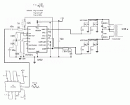
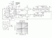
The circuit doesn´t work. You must provide some method to remove gate charge of power mosfet´s, must use SG3525 which is push pull output (Totem Pole). In your way both mosfet will be on in the second clock pulse, then they will explode.
I´m working in the same idea like your, but in other way. Mine is as follows: HCF4060 oscillating with remote control 450KHz resonator. On Q13 obtain a 55.5Hz, low pass filter (1/2 TL082) gives quasi senoidal waveform. Q4 gives 3.5KHz, integrating it (2/2 TL082) gives triangular. Comparator (TS3702) between them gives PWM easy signal. HCF4049/4050 generates 180deg out of phase gate mosfet signals. A 12+12/315VCA gives 220VRMS quasi senoidal PWM. It is currently under design, but it is working.
No alarms, no protection, only a 15Amp fuse.
Best regards.
Hello
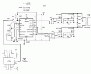
I can't find any SG3525 here around, so I've redone my SG3524 schematic for a better turning off of the mosfets, as you suggested.
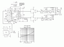
Is it better in my ver.3 schematic ?
I know that I won't get a very good sine at the transformer output, but maby adding a negative feedback from the transformer output to the SG3524 input will do a better sine, wich side of the transformer output I use for a nfb ?
Thank you
Bye
Gaetan
Attachments
Last edited:
Now the circuit is better, but still will not work. The 1K resistors must be moved to the base of the transistors, because the PNP device will be not properly biased at turn off, since 3524 is open emitter/collector.. And, you can increment the value to 10K to drain less current from inside transistors, 1K means 12mA at 12V and such a current is not dangerous, but not necessary.
At the output of the transformer, if the load is a resistance of R ohms, the current will be R times scaled the same voltage waveform. But if it is inductive, the CURRENT will approximate to a senoidal one, but voltage always will be still a PWM. So, if you want to BFW the output, you must integer (Say, low pass filter at a cutoff frequency several times (5 to 10) lower the PWM frequency) the output to recover the senoidal wave, and a servo (Like an Op amp) substracting the sample above mentioned from that of the XR2206 generated. But XR2206 is a bit expensive to this function, why not to use a single opamp in wien bridge?
Good luck.
How do you intend to get a sinewave output? You also need feedback for the output to regulate the output.
Good theoretical questions.
The 8038 creates a sine wave and the '24 a pwm version of it. The transformer is often enough of a low pass filter.
Generally the source impedance is low enough you don't! The lightest load will normally drop the open circuit voltage to the target voltage so no light load resistor is required in most cases.
simon,
The transformer will not act as a filter. (If is does, it is a really poor transformer.) So some method of converting the bipolar PWM pulses to a sine wave must be provided. You need a synchronous rectifer and filter to do this. You also need feedback if you hope to get a decent quality sine wave of the correct amplitude. Gaetan needs to figure out how to do this, or someone needs to help him, if he doesn't know.
The transformer will not act as a filter. (If is does, it is a really poor transformer.) So some method of converting the bipolar PWM pulses to a sine wave must be provided. You need a synchronous rectifer and filter to do this. You also need feedback if you hope to get a decent quality sine wave of the correct amplitude. Gaetan needs to figure out how to do this, or someone needs to help him, if he doesn't know.
simon,
The transformer will not act as a filter. (If is does, it is a really poor transformer.) So some method of converting the bipolar PWM pulses to a sine wave must be provided. You need a synchronous rectifer and filter to do this. You also need feedback if you hope to get a decent quality sine wave of the correct amplitude. Gaetan needs to figure out how to do this, or someone needs to help him, if he doesn't know.
Hello
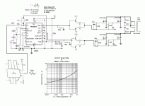
Maby adding a negative feedback from the transformer output to the SG3524 input will do a better sine like in my new schematic ?
Thank
Bye
Gaetan
Attachments
Last edited:
simon,
The transformer will not act as a filter. (If is does, it is a really poor transformer.) So some method of converting the bipolar PWM pulses to a sine wave must be provided. You need a synchronous rectifer and filter to do this. You also need feedback if you hope to get a decent quality sine wave of the correct amplitude. Gaetan needs to figure out how to do this, or someone needs to help him, if he doesn't know.
I'll take it you have never built one or even taken one apart. The modern flatpack designs roll like a rock below 400 Hz. The split bobbins go a bit higher. The only power transformers that couple much higher are the secondary over primary types.
We are not talking about audio transformers here.
In practice, the transformer IS a filter because of it parasitic elements, but normally they are designed to not interfere with the frequencies (And them in the waveform of interest) that he must pass.
In other hand, the drive circuit looks fine, but I get rid for the cap and resistor in he gate of the MOSFET´s (100R // 100nF), and connect them only a 4.7 to 10R 1/2 watt, without capacitors.
The negative feedback can´t be done so easy. First, you must ground the opposite side of the winding. Second, you must ensure that phase rotation inside circuit can be tolerable when closing the loop. Third, you must use servo circuit. It implies an opamp, in where the NI input gets the original sinewave, previously conditioned in amplitude accordingly the common mode of the OP selected (The JFET is the best for it kind of job. Then, you must bias it properly, a bipolar (+12 /-12V is usually to proper job of the opamp). At the inverting input, you will inject the feedback signals, whit more or less same considerations above told. And then, you can close the loop. This finish with the proper selection of frequency response of the servo for the entire set not to oscillate ´n´mantain the output level and wave form.
Or you can use the internal opamp, but it is difficult to explain in words how to do such a circuit. 1K +10n at comp pin must be erased, like all components at pin 1. Pin 1 to pin 9 must have a RC network to ensure system stability, not so easy to explain here (I redirect you to a work called "Closing the Loop" by Lloyd Dixon, in TI application notes SLUP068.) At pin 1 also came the signal from OP trafo with such a network to properly "decode" the sine signal from the PWM at the out of the trafo, and then the internal OA makes the changes in the signal to proper job of the circuit.
In last, the feedback between pin 9 (compensation) and pin 2 (Inv. Input) does do nothing. It is bad designed. Some resistors and capacitor put there without any calculation is of no sense.
I suggest you to learn some works about servos before start such a design, for your own security, time waste and semiconductors money spent. A good design isn´t a blend of individual subcircuits, each one must be carefully brained.
Best regards.
Last edited:
simon,
I don't understand post 14. What do you mean by flatpack?
I think he is talking about small flat transformers, usual called "planar" in which windings are inside of the copper traces of a PC board, very common actually for small power SMPS´s.
OK, but so what? It most likely will saturate at 400 Hz, but who cares, because it operates at 4 KHz. You still need a synchronous rectifer circuit and filter in the output side of the transformer. The comment "We are not talking about audio transformers here." doesn't make any sense either.
OK, but so what? It most likely will saturate at 400 Hz, but who cares, because it operates at 4 KHz. You still need a synchronous rectifer circuit and filter in the output side of the transformer. The comment "We are not talking about audio transformers here." doesn't make any sense either.
Yes, I agree, but don´t forget that switching and audio transformers have similarities in the particular sense of power and high frequency passes thought them.
He don´t need a rectifier, he can put a LC filter integrating the waveform to recover the sine amplified, but in most cases it is not necessary because almost all sine inverters for AC induction motors directly gives the PWM at their output, and motors run OK from them. And lamps or heaters also do.
Last edited:
Simon is talking about extra low profile conventional transformers.OK, but so what? It most likely will saturate at 400 Hz, but who cares, because it operates at 4 KHz. You still need a synchronous rectifer circuit and filter in the output side of the transformer. The comment "We are not talking about audio transformers here." doesn't make any sense either.
What is used here is the leakage inductance of the transformer combined with the mains suppression capacitor to form a low pass filter.
The average content of the PWM waveform is 50 or 60Hz, and that's what is finally left.
It does work quite well, and can even be used with an old style, superposed windings transformer.
The only types that are completely ruled out are toroidals.
- Status
- This old topic is closed. If you want to reopen this topic, contact a moderator using the "Report Post" button.
- Home
- Amplifiers
- Power Supplies
- About my pwm sine inverter
