Just read several hundred pages of forum threads and I'm coming up blank (but I'm a lot smarter about regulators in general the the muppet's swedish chef). I'm building a couple of amps - LM3886 and Elliot P101 - and I'd like to play with some high bandwidth, high current regulated supplies. It seems that there have been boards made on and off, but I can't find anyone still producing them. I'm thinking on the order of 5-6 amp output. Any pointers? Artwork would be useful too, I can probably make my own boards if I need to, but pre-made boards would jumpstart the project.
thanks
Jim
thanks
Jim
Just read several hundred pages of forum threads and I'm coming up blank (but I'm a lot smarter about regulators in general the the muppet's swedish chef). I'm building a couple of amps - LM3886 and Elliot P101 - and I'd like to play with some high bandwidth, high current regulated supplies. It seems that there have been boards made on and off, but I can't find anyone still producing them. I'm thinking on the order of 5-6 amp output. Any pointers? Artwork would be useful too, I can probably make my own boards if I need to, but pre-made boards would jumpstart the project.
thanks
Jim
Why do you need a Jung super regulator in the first place? There are clearly advantages to that design, but every design is a balance of factors and the JSR was never really intended to supply high current. Kind of like trying to fine-tune a firehose
")
Why do you need a Jung super regulator in the first place? There are clearly advantages to that design, but every design is a balance of factors and the JSR was never really intended to supply high current. Kind of like trying to fine-tune a firehose
Not sure that I really do need the Jung design. I'd like to see what difference an ultra low impedance wide bandwidth supply makes in a solid state amp. Bill Johnson (Audio Research) said in an interview that the power supply is critical - it's part of the signal path and makes a huge difference in the sound. He was a proponent of isolated super stiff power rails. Based on my experience with ARC tube stuff, I'm willing to buy his argument. Why Jung? The design is reasonably easily implemented, specs out really well, has remote sensing, and has a low dropout voltage. I'm definitely open to other ideas, but the silence on my thread seems to indicate I'm headed off in a direction that might be unusual. Is there a better high performance regulator topology for a power amp?
So what I'm thinking is this.. I have an Audire chassis with a very conventional old school bridge plus huge caps power supply. I'm build a LM3886 chip amp into the chassis and I'll try it with the current supply and take some measurements at the board V+/V- inputs of noise, voltage, ripple, and hopefully frequency response and listen to it. Then I'll probably update it with a more modern fast rectifier multi-cap PS, and measure and listen. Then I'd like to put in a top notch, remotely sensed regulator and do the same. Phase 1 is going together now, and if I can find a few more hours this weekend I should be listening to it Sunday night.
Jim
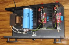
Spent some time thinking about whether power supplies were an issue and took my chipamp down to the bench for some measurements. The amp seems pretty healthy and is reasonably well built. As you can see in the picture, it is built into an Audire chassis, using the Audire power supply save for a lower voltage Stancor P-8619 192VA 24/0/24V transformer. At clipping it puts out 57W into 8 ohms, both channels driven. More importantly, it sounds pretty good, far better than I expected for such a simple design. pic attached
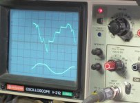
Measuring the power supply at full power output the rails drop from 35.0V to about 31.7V with the 120hz ripple at about .5V p-p. That seems pretty soft to me although I'd say the PS is built to reasonable standards. I took a bunch of pictures of the rails at full output at various frequencies, and the pic posted is at about 25hz. The top trace is the rail at about .5v/division, so there's nearly 2.5 volts of noise. Looks pretty ugly. I also took some video of the rails bouncing to time with the music which is amusing, but probably not worth the work of putting it up on youtube.
Anyway, this is why I want to tinker with power supplies - I'm thinking that this kind of crap on the rails is probably audible, and I'm going to put use this amp as a base to play around with some different supplies. The next supply will be dual (one for each channel) chipamp.com supply boards with 15,000 uF caps and fast rectifiers, and I really want to try a regulated supply. More on that in the next post.
Attachments
Since this thread wasn't exactly overrun with suggestions on how to build a good regulated supply, I started thinking about the easiest way to do it. (always dangerous...) My first thought was just to scale up the Jung design, run a higher current opamp with hand selected high gain transistors, etc., but that involves a fair amount of development and testing. Then it came to me - why not just use the LM3886 as a regulator? (and I'm asking for feedback on this) The thing specs out pretty well, and I'm convinced that there's enough power dissipation and current output to work. And it's really easy since I bought a bunch of boards from chipamp.com so I have four extra for two channels of +/- regulators.
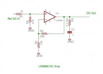
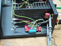
So I tested the idea tonight. Took the LM3886 amp that I built last week downstairs with the idea of changing it to the attached circuit, which is of course just a standard chipamp circuit with the cap removed from the feedback circuit so we have gain at DC, and the overall gain reduced to around 3.something. You can see in the picture that I mounted a 22uF poly cap offboard instead of the electrolytic spec'd and that was a stroke of luck since I could just temporarily replace it with a flying resistor. Took about 30 seconds to turn my audio amp into a variable DC power supply. I connected a pot to a 6V battery to have a variable DC input to test. It works.
From the limited testing I did, the LM3886s put out near 5 amps with about a 3v drop. No sign of ripple on the output so long as there was 3v or so difference. I didn't have a load to see how far I could take the current before it hit limiting so it might go well over 5A. The load resistors got really hot since I was dissipating 127watts, and one of my 8 ohm load resistors became a fuse at about 4 amps which sort of limited my testing. So I'm not sure how much current these things are capable of. I'm guessing that with music as a load they're not likely to current limit until well over 5 amps, and that is plenty of power supply for a single LM3886 amp channel. When I was testing, I left things run for minutes at a time at full load and the amp heat sinks barely got warm. The chips are nowhere near their dissipation limit of 125W and the current limiting spec is 7A min, 11.5A typical. (before thermal derating)
At this point I'm planning on building four more of these amps for two channels of +/- rails. Fortunately I have a slightly higher voltage/VA transformer that came with the Audire chassis so I can keep the rails at about 35V even after the regulator voltage drop. Then comes the real test - does it sound any better?
Am I missing anything? Will this thing be stable? Opinions appreciated.
Attachments
Last edited:
no reason it shouldnt work just fine. the other options you have are to use an opamp with mosfet or power transistor follower, paralleled lm317/337 etc
I dont know that i would call a jung reg low dropout, particularly with prereg. you could look into the coffin gold minireg regulator design, with a few changes of transistors, to higher HFE versions you could probably make what you need
I dont know that i would call a jung reg low dropout, particularly with prereg. you could look into the coffin gold minireg regulator design, with a few changes of transistors, to higher HFE versions you could probably make what you need
Thanks. Minimum Av is 10 and I assume this is for stability, which I need to look at.post5
the gain ratio of 39/12 is outside the National recommendation.
@qusp - thanks for the link to the minireg. LM3886 is easier since I have the boards.
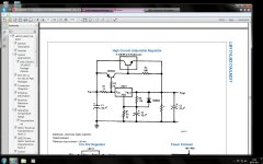
Why not use an LM317/LM337 with a pass transistor iaw the datasheet.
yep, thats what i was suggesting, i plan to try this with 'the wire' not exactly efficient, but should work well.
@ Jim: no problem I understand the want to try what you have in your possession first
A general bias against 3 legged regulators in audio use. Seriously, I have used a lot of 317/337s, including with pass transistors, and I was hoping to find something better. The Salas/Jung regulators have been pretty widely praised for their sonics, and I wanted to try a better regulator in a power amp. My thinking is that it could make a substantial difference - if you look at the junk on the rail in my earlier post, it's far worse than anything you'll see on power supply at the preamp level.Why not use an LM317/LM337 with a pass transistor iaw the datasheet.
Anyway, I haven't tested the output impedance and stability of the LM3886 in a power supply application (or listened to it), but I'm hoping that it will have lower output impedance and better frequency response than the 317. Before the LM3886 idea, I was thinking about paralleling the higher current 338s, but there is no negative voltage version of that part (or any high current regulator that I could find). The 317/337 + pass transistor approach definitely works and would be a big improvement over what I've got now.
The LM3886 has quite a good PSRR. You can't go far wrong with a big transformer and a good CRCRC supply. Or even better a CLC supply.
The big transformer will have fairly good regulation and the CRC will kill most of the line noise whilst maintaining a fairly low impedance to keep the BASS rigid and firm.
Bypassing the final C with a succession of smaller caps will help to brighten up the TREBLE.
The big transformer will have fairly good regulation and the CRC will kill most of the line noise whilst maintaining a fairly low impedance to keep the BASS rigid and firm.
Bypassing the final C with a succession of smaller caps will help to brighten up the TREBLE.
One thing you could think about.
You are going to need a serious Pass transistor or MOS-FET in order to achieve the currents that you are after.
The simple LM317/337 can be improved by adding a shunt regulator to them.
It's inefficient to use a Shunt regulator with a Class A/B amp but you would reduce any noise by adding the shunt at the drive to the pass transistor.
- Status
- This old topic is closed. If you want to reopen this topic, contact a moderator using the "Report Post" button.
- Home
- Amplifiers
- Power Supplies
- High Current Jung Regulator Board?