Not sure this is the right place for such questions but here goes nothing.
For a power supply i need a power load that is independent of the voltage.
I'm not talking about a current source, the power load of a current source will rise if the voltage gets higher.
So i need a load that will draw a load of 1,5 watts from 4-65 volts all the way.
Can any one help me ? i have done some thinking but I'm a bit stuck.
There are a few restrictions, i can not use a negative voltage because the supply does not have one. i have a 5v supply for powering the components.
The 1,5watt should be dissipated in a to-220 transistor e.g. bd139.
No more then 3 opamps of 324 type(these opamps should be power from the 5v supply).
hope some one can help me out
Its not for testing, i want to use it to load a variable switching supply.
If i just use a plain resistor then it will only load the supply in the higher voltage region.
If i use a current source then it will draw excessive power in the higher voltage region, but will load the supply all the way down to 4v.
The thing is i want to waste as less power as possible.
I was mebay thinking of using a AD633 Analog Multiplier but is this not a bit overkill ?
Something that draws the same (or similar) power regardless of voltage...
Another switching power supply, loaded by a resistor or something.
Great idea, but a bit overkill to i think
A constant power load itself is stable; however, due to the negative incremental resistance the power supply may become unstable. It depends on the supply.
egbert, you want to make P=V I a constant, so so you need to masure the VI product and make it constant. Obviously, this requires some type of multiplier. Also note that you need to limit the current at low voltages; otherwise it will become very large.
egbert, you want to make P=V I a constant, so so you need to masure the VI product and make it constant. Obviously, this requires some type of multiplier. Also note that you need to limit the current at low voltages; otherwise it will become very large.
The voltage across a diode is proportional to the logarithm of the current. If you use Vbe of a BJT then this is quite accurate. Put a current proportional to the PSU voltage through one diode (just use a resistor). Put the load current (or a fraction of it) through another diode. Add the two voltages together with a summer. Arrange a feedback loop to keep this sum constant. If the sum is constant, then the product of I and V will be constant.
The voltage across a diode is proportional to the logarithm of the current. If you use Vbe of a BJT then this is quite accurate. Put a current proportional to the PSU voltage through one diode (just use a resistor). Put the load current (or a fraction of it) through another diode. Add the two voltages together with a summer. Arrange a feedback loop to keep this sum constant. If the sum is constant, then the product of I and V will be constant.
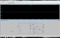
This seems to work but I'm not getting really accurate results in my simulation model. tomorrow i will overview it.
Thank you all for al your help so far.

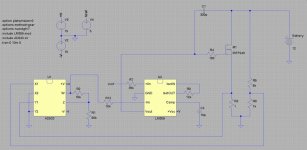
I'm working on a constant power load for burn testing battery packs using an AD633 and an LM359. The AD633 is in the feedback loop of the LM359. Current is sampled via a resistor and voltage is sampled via a resistive divider. The voltages representative of current and voltage are sent to the AD633 and scaled. The output of the AD633 is a voltage representative of power consumption and is converted to a current and fed to the LM359 where it is compared to a reference current that defines the total consumption of the circuit.
Attachments
I had an idea that might work. If you took a Thermal-Trak transistor like the NJL3281D and measured the voltage drop across the internal diode while the transistor (no heat sink) is dissipating 1.5W and use this value to control the switching point of an op-amp driving the base of the transistor. This would control the temperature rise of the transistor and the power dissipation. Of course your load power would also be affected by ambient air temperature and the air flow over the transistor.
If you are load testing batteries then this should respond quick enough.
If you are load testing batteries then this should respond quick enough.
Last edited:
I have absolutely no idea how to get rid of the threshold problem.
I think the circuit is very prone to any thermal changes.
"jkuetemann" i already suggested to use the AD633, the problem is it will need a negative and positive supply to work, and the chip is expensive.
"RJM1" your idea looks simple, and i think it will work fine but such transistors are expensive.
Are there any other transistors with an internal resistor or diode that are cheap?
You could always use any transistor with a diode mounted to it although, the thermal lag between the temperature rise in the transistor and the change in temperature of the diode could be several seconds. This could make the start up current higher than what you want for several seconds, or complicate the circuit to add a slow start.(10s of seconds)
Last edited:
- Status
- This old topic is closed. If you want to reopen this topic, contact a moderator using the "Report Post" button.
- Home
- Amplifiers
- Power Supplies
- Voltage independent power load