Tried to discuss this on another forum but unfortunately that forum is a soap box for the hosts to sell their product. Anyway, which is better in the case of a Dynaco Stereo 70 amplifier? Some marketing Dynaco kits feel the factory type multi cap is better. Others like myself like the power supply replacement cap board like Geek and triode sell.
My feeling is this... the stock Dynaco is anemic sounding mainly because it suffers from a poorly designed power supply. The filter cap is too small and the life expectancy of it is rather short. The add on power supply board not only allows one to choose an array of caps that will help the amplifier perform like it should but also allows for individual cap replacement instead of replacing the multi cap. One can also choose caps with a 105c rating as opposed to a 85c rating.
If one insists on the Dynaco looking factory then leave the multi cap on the chassis for looks or gut the thing and install different caps in it.
I am wondering what others think of the comments I have made so far.
My feeling is this... the stock Dynaco is anemic sounding mainly because it suffers from a poorly designed power supply. The filter cap is too small and the life expectancy of it is rather short. The add on power supply board not only allows one to choose an array of caps that will help the amplifier perform like it should but also allows for individual cap replacement instead of replacing the multi cap. One can also choose caps with a 105c rating as opposed to a 85c rating.
I would go this route.
After all you want to listen to it, not look at it.
I think the ST-70 is common enough you could always find a second one to restore to factory looks and specs if you want to.
I think that the decoupling caps that are (or should be) RIGHT AT the power devices are just as important as the PSU filter caps (if not more important). They determine the transient response, and also prevent the power rail voltages from being excessively disturbed by the transients.
They act like small point-of-load PSUs for the fast transient current demands, which would otherwise be inaccurately rendered because of the parasitic inductance of the power rail conductors, which would also cause large voltage excursions on the rails.
So I would want to beef up both the PSU caps and the decoupling caps.
For the decoupling caps, the total length of the connections (plus the caps' lead spacing) matters very much, because of the parasitic inductance. So it's better to parallel some smaller caps instead of using one big cap, including paralleling their leads or connections all the way to the power device, to get the maximum inductance reduction from paralleling.

Mr. Goottee, What distance would be small enough that you would not need decoupling caps?
How much does the voltage play into this, would you have the same level of concern with a tube amp vs. a lower voltage solid state amp? (regarding distance from power load to cap)
Thanks.
How much does the voltage play into this, would you have the same level of concern with a tube amp vs. a lower voltage solid state amp? (regarding distance from power load to cap)
Thanks.
Mr. Goottee, What distance would be small enough that you would not need decoupling caps?
How much does the voltage play into this, would you have the same level of concern with a tube amp vs. a lower voltage solid state amp? (regarding distance from power load to cap)
Thanks.
It depends on the peak current that might be needed, and its worst-case (shortest possible) risetime, and on the voltage rail disturbance amplitude that one is willing to accept. But it could be a very short distance, in the worst-case transient-current scenario for a particular amp.
Even just for an LM3886 chipamp, even WITH decoupling caps, in order to not disturb a power rail by more than 0.1 Volt (very stringent, I admit) the distance to the decoupling caps might be on the borderline of being too great (something like one inch round trip was needed), which might require the decoupling caps to be decomposed into multiple smaller paralleled caps (with parallel connections too), to lower the parasitic inductance enough. And that was for a relatively-low required capacitance (220 uF).
I would probably say that large-ish decoupling caps are "always" needed. But I guess there could easily be cases where they are not, especially if the distances were less than an inch or two. But even a lot more distance would be fine if the worst-case rail-disturbance amplitude didn't matter much, and maybe also if you didn't care about the most-precise reproduction of transients, or had low bandwidth (maybe 22 kHz instead of 250 kHz).
Every design will be different. And sometimes it might matter and other times it might not (and I am talking "worst case", which will rarely come into play, anyway). For my own amplifiers I like to err on the side of overkill, so I don't have to wonder as much about "what might have been". But it is usually quite difficult, even just physically/mechanically, to get a lot of decoupling capacitance close-enough to each power device, with low-enough parasitic inductance.
This is actually still a new concept, for me, that I was trying to put numbers and equations to in the last half of the thread at:
http://www.diyaudio.com/forums/power-supplies/106648-paralleling-film-caps-electrolytic-caps.html
Look at posts 221 and 224, with some more in post 252, which led me to do posts 310-314 and 319, and 341.
a motor start cap 150uf-330uf with a .1 poly and a .022 pio cap in parallel.
and 5Uf poly for coupling, with a .01 pio cap just to make the snooties snoot more
oh yea if you feel adventurous, try some Mills MRA resistors, especially the cathode and grid circuits.
now, I have to go do some more mad scientist magic.......
and 5Uf poly for coupling, with a .01 pio cap just to make the snooties snoot more
oh yea if you feel adventurous, try some Mills MRA resistors, especially the cathode and grid circuits.
now, I have to go do some more mad scientist magic.......
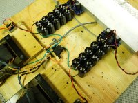
Thanks for the links Tom, I a read them once before, I am going over them again.
The reason I ask was kinda chip-amp related slightly off-topic.
You can see in my photo what I was getting at. (breadboard stage)
I almost have my smoothing caps right at the amplifier board. I can get even closer, at which point the line was starting to blur as to what is a smoothing cap and what was a decoupling cap.
I had thoughts of literally having the amplifier board sitting right on top of the last "smoothing" cap. I was thinking of removing the 1000uf Panasonic decoupling cap effectively leaving me with a 4700uf decoupling cap.
Attachments
Thanks for the links Tom, I a read them once before, I am going over them again.
The reason I ask was kinda chip-amp related slightly off-topic.
You can see in my photo what I was getting at. (breadboard stage)
I almost have my smoothing caps right at the amplifier board. I can get even closer, at which point the line was starting to blur as to what is a smoothing cap and what was a decoupling cap.
I had thoughts of literally having the amplifier board sitting right on top of the last "smoothing" cap. I was thinking of removing the 1000uf Panasonic decoupling cap effectively leaving me with a 4700uf decoupling cap.
Ideally, that would be a good/great way to go. But if you can also get a 220uF or more on the back side, or, better yet, soldered directly to the chipamp pins, go for it!
- Status
- This old topic is closed. If you want to reopen this topic, contact a moderator using the "Report Post" button.
- Home
- Amplifiers
- Power Supplies
- multi cap verses add on power supply board