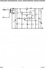
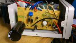
TA2020 is fairly tolerant of power rail noise, what you have will probably be fine... but since you asked.
The PSU uses a half wave rectifier subcircuit, full wave would be better. A voltage regulator IC should be lower noise than that too. C3 could be raised in capacitance and a good brand low ESR capacitor. How will the case lid fit with that big 10KuF cap there? While it will reduce pre-regulated ripple, that much capacitance isn't really needed in front of a regulation circuit for TA2020.
Consider if it's driving 8 ohm speakers, the datasheet claims 88% efficiency @ 12W/8 Ohms. That's less than 1A current. Even if driving 4 ohm load, THD shoots up really fast past about 13W output, still around 1A.
If you made these changes it's quite possible (probable, IMO) the amp won't sound any different (for better or worse).
You maybe right, its a bit overkill for this amp to have such big capacitor , i just took what i had.Also the power is enough i suppose but, i tried some different supplyes and
they all sound different.An computer PSU didnt sound good at all.So i just wonder if its any magic in some?Or is it just enough power and a big capacitor?
Just trying do understand the difference.
And the 10K capcitor is standing up now.
they all sound different.An computer PSU didnt sound good at all.So i just wonder if its any magic in some?Or is it just enough power and a big capacitor?
Just trying do understand the difference.
And the 10K capcitor is standing up now.
^ Most likely the bad result with a computer PSU was that being a switching PSU, it introduces more errors. IMO, there's a lot more difference between regulated switching PSU and linear than even between regulated and unregulated linear for a chipamp.
Here's another thing to try - jumper from the 10K uF capacitor straight to the amp to see how that sounds, EXCEPT the voltage is probably too high with that particular transformer with it having enough voltage margin to be 13.8V after regulation. Maybe a couple silicon diodes in series would drop enough voltage.
Here's another thing to try - jumper from the 10K uF capacitor straight to the amp to see how that sounds, EXCEPT the voltage is probably too high with that particular transformer with it having enough voltage margin to be 13.8V after regulation. Maybe a couple silicon diodes in series would drop enough voltage.
Code:
C3 could be raised in capacitance and a good brand low ESR capacitor.
Code:
Here's another thing to try - jumper from the 10K uF capacitor straight to the amp to see how that sounds, EXCEPT the voltage is probably too high with that particular transformer with it having enough voltage margin to be 13.8V after regulation. Maybe a couple silicon diodes in series would drop enough voltage.So, a few silicon diodes could drop the voltage, good to know.
Im still an newbie in this.
Thanks for your help.
3 silicon diode in series would drop about 0.6V to 0.7V each, bringing 16.8V down to about 14.7V, close enough to the 14.6V limit on the spec sheet... or add a 4th diode to drop to 14.0V. Then again if you're dropping this much voltage you could experiement with a regulator IC too like LM317.
I've never powered a TA2020 with LM317 regulated supply but am happy with a TA2024 amp I paired with one. It seldom consumes more than about 400mA current, I'd expect a 1.5A regulator like LM317 to be enough for a TA2020 provided a decent sized heatsink is on it.
I've never powered a TA2020 with LM317 regulated supply but am happy with a TA2024 amp I paired with one. It seldom consumes more than about 400mA current, I'd expect a 1.5A regulator like LM317 to be enough for a TA2020 provided a decent sized heatsink is on it.
Changing C2 from 100uF to 1000uF would give you about 10db more power supply ripple
rejection at 100hz but this would also increase the time it would take the power supply to reach the final 13.8V from 0.5 seconds to 5 seconds. (slow start)
Is that good?I mean in general now, the TA2020 dont need it i think.
To get more power ripple?
Wich means?
Sorry for newbie questions...
Aha, nice!Ripple rejection. It means that the amount of hum from your power supply would be lowered by 10 db. Less hum. The hum would be half as loud.
I found only one 680uF in the scrap yard that i mounted, it goes from 0V to about 10 and the jumps to 13,5V under a second.
For diodes I was thinking of standard 3A silicon diodes, which come in lots of part #s, one of the most common being 1N5401 (through 1N5408). Just don't use schottky diodes since they have a much lower forward voltage drop.
TA2020 is pretty good about low frequency ripple rejection, it benefits less than most (chip)amps from reducing linear PSU ripple.
TA2020 is pretty good about low frequency ripple rejection, it benefits less than most (chip)amps from reducing linear PSU ripple.
Last edited:
- Status
- This old topic is closed. If you want to reopen this topic, contact a moderator using the "Report Post" button.
- Home
- Amplifiers
- Power Supplies
- PS1303 Power Supply improvement?

