I have no idea what this is called, but i found such description :
 Previously it was only creating noise, but few days ago it fry one of my amplifier component
I'm curently searching for power supply circuit that comprise/incorporated protection/stabilisation for main supply "madness"described above.
Due to few days ago the main supply burst my DIY amplifier when I switch off my toilet bulb....Quoted from : Understanding, finding, & eliminating Ground Loops by Bill Whitlock
Power-line voltage normally consists of a broad spectrum of harmonics and noise in addition to the pure 60 Hz sine wave. The noise is created by power supplies in electronic equipment, fluorescent lights, light dimmers, and intermittent or sparking loads such as switches, relays, or brush type motors (blenders, vacuum cleaners, etc.). The drawing at right shows how sudden changes in load current caused by an ordinary phase-control light dimmer generate high-frequency power line noise. At high frequencies, a building's power wiring behaves like a system of mis-terminated transmission lines gone berserk, reflecting high frequency energy back and forth throughout the building’s wiring until it is eventually absorbed or radiated
Previously it was only creating noise, but few days ago it fry one of my amplifier component I'm curently searching for power supply circuit that comprise/incorporated protection/stabilisation for main supply "madness"described above.
If i'm not wrong, EMI is disturbance that affects an electrical circuit due to either electromagnetic induction or electromagnetic radiation emitted from an external source. Of course my situation will produce some, but i don't think that is what I describe, and EMI is insufficient to blow my fuse and component in fraction of micro second...
is there any way to protect against it ? just don't like my amplifier destroy innocently....
is there any way to protect against it ? just don't like my amplifier destroy innocently....
Last edited:
In your case, i think its a voltage surge created when switching mains devices so you may want to try adding a surge protector circuitry, it is usually done with a varistor.
Surge protector - Wikipedia, the free encyclopedia
This is likely to happen if you live in rural areas and the mains supply isn't very good.
Surge protector - Wikipedia, the free encyclopedia
This is likely to happen if you live in rural areas and the mains supply isn't very good.
Use 265Vac varistors after main fuse, and assure it can handle for schortcircuit, a current bigger than main fuse.
If main supply have spikes, more than 265Vac, the varistor will act like an shortcircuit, blowing main fuse.
Better to burn a main fuse, instead an amplifier.
I think you have SMPS power supply of your diy amp.
If is normal trafo, is possible to give him too much supply, at normal main voltage (overvolt), and when main voltage raises a bit, is enough for the amp to fail...
Last edited:
well... it is using toroid trafo, power supply doesn't fail. The should able to withstand little bit of overvolt you mention. The amplifier also fails in a special way, that only one half of is destructed, another half didn't blow its fuse and components.
Is there any simple implementation of circuit ? If it is high frequency energy, is a zener/regulator & inductor enough to block/limit it ? would like to know what will those 2 component and varisotr installe at power supply will effect the audio quality ?
Is there any simple implementation of circuit ? If it is high frequency energy, is a zener/regulator & inductor enough to block/limit it ? would like to know what will those 2 component and varisotr installe at power supply will effect the audio quality ?
this type of surge protection seems what i'm thinking : Series Mode (SM) surge suppressors
which consist of several of capacitor & inductor & resistor. But seems the cost is high, but i'm thinking to make it only for those spike of I had mention, not lightning thunder, so would reduce the cost alot I guess. Have no idea how to incorporate in circuits... hope someone would point out me how to do so.
which consist of several of capacitor & inductor & resistor. But seems the cost is high, but i'm thinking to make it only for those spike of I had mention, not lightning thunder, so would reduce the cost alot I guess. Have no idea how to incorporate in circuits... hope someone would point out me how to do so.
hm.... not sure about it, but sure happen fast enough. Never happen before though.... I think of incorporating varistors in main circuit and secondary circuit, as well as incorporating filter which consist of caps, inductor, resistor. This should give a good stable supply of electricity under most condition, since it suppress spike and ripple, at the same time limiting surge by varistor.
After some reading, I found that the varistor is quite similar to zener diode.
After some reading, I found that the varistor is quite similar to zener diode.
Standard surge protectors will be too slow (varistor). Spark gap arrestors will handle a lot of power as do transorb's. Ideally you would use a parallel arrange where yo have a fast protection device paralleled with a slower part that can handle more power. An example would be a transorb paralleled with a varistor. Set the first part at a higher clamp voltage than the second. The transorb would clamp until the varistor can take over.
Tony
Tony
hm... it seems spark gap arrestor is quite expensive. I'm thinking of using varistors paired with inductors, maybe also capacitors. But I have no idea what value should be practical for LC circuit of this type (surge protection).
My idea is like SM(series Mode) surge protection paired with conventional cheap method. (varistors)
I would also like to know what happens if a varistor fail, does it connect (fused together) or disconnect (separate leads) ?
My idea is like SM(series Mode) surge protection paired with conventional cheap method. (varistors)
I would also like to know what happens if a varistor fail, does it connect (fused together) or disconnect (separate leads) ?
Some incandescent bulbs produce an arc when they fail, often blowing a fuse. This sudden surge in current, followed by a sudden drop, will maximise any back emf from the inductance of your mains wiring. My guess is that inductance can be increased by the habit of some electricians (in the past?) to use individual wires in conduit rather than a multi-core cable (e.g. twin and earth). Curiously, this form of wiring was/is regarded as 'more professional' than multi-core. Now if they twisted the wires together this would reduce inductance but they never do this because it makes it much harder to pull a wire through the conduit.
Pick the protection from another circuit ?
Following attachement is a schematic taken from a CRT monitor PCB. I scavenged it and now 'should' be able to put in use.
Wanted to ask, is the following circuit is a surge/spike supressor ? If suitable then i'm going to use.
Another question is in the diagram, which what is the description of L601 means ?
Attachments
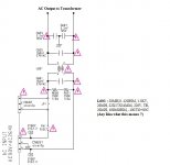
Its called a Mains EMI Filter. Sometimes if the mains line is very bad, a surge protection is also added to prevent the large voltage spikes from entering the amp.
"SOMETIMES" Mains power is sufficient to power inductive motors and light bulbs. It if full of garbage that at the extreme can damage or cause instability. More common is the amount of noise and sometimes that makes it through to the main rails. I was amazed when looking to see if my new FRED rectifiers had any ringing (no) how much HF crud made it through the power supply. PSRR is a last defense, not the best. I have changed my old opinion that only a good suppressor is necessary if you have e-core linear power supplies. In only a couple of days since adding an internal twin-T filter to a plate amp, it no longer turns itself on when the system is off. That should be a hint.
Go the CORCOM site and read about filters. See how different designs filter different problems. Then go to places like Furman, Tripp-Lite, Panamax to find products that may help. I will refrain from DIY solutions as they involve working with mains. That has safety as well as regulatory issues this site can not support. As much as I criticize them; UL, CSA, and others do help keep us from burning down our house or electrocution.
Post 16, that filter is only enough to keep the CRT from putting too much garbage back on the line. Not sufficient as an input filter to audio. Better than nothing though.
Ground loops can be another problem. For instance, I found my house had, illegally, two earth rods that were not connected. It caused a few off hum problems when I connected my outside antennas. Problem solved when I brought it up to code. Also to remember, the safety ground (green) can have just as much noise on it as neutral. Noisy ground is just as big an issue.
Ground loops can be another problem. For instance, I found my house had, illegally, two earth rods that were not connected. It caused a few off hum problems when I connected my outside antennas. Problem solved when I brought it up to code. Also to remember, the safety ground (green) can have just as much noise on it as neutral. Noisy ground is just as big an issue.
My guess is L601 is 20mH inductance, 0.42ohms series resistance, 1.5kV voltage withstand, meant for use on up to 220V supply, 100M insulation resistance, usable from -10C to +85C temperature. Its the kind of full component spec you would get on a datasheet. As this inductor is in the mains supply you can't just substitute any old 20mH choke. Oh, and its size is 22mm x 17mm x 34mm. You have to bear in mind that people who produce drawings and manuals don't always understand that in science and engineering 'm' and 'M' don't mean the same thing - there is a 10^9 ratio difference.
If this sort of thing puzzles you then you should not attempt to make your own mains filter. Instead, buy a packaged one.
If this sort of thing puzzles you then you should not attempt to make your own mains filter. Instead, buy a packaged one.
#13 MOV's short. ALWAYS be sure protection systems are inside the fuse protection. X and Y caps are designed not to cause electrocution or fire on fault, but "designed to" and real are two different things.
A really good twin T filter costs maybe $40 for a 30A, $15 for a 3. Half that on e-bay. Much safer than DIY and designed by engineers who understand the problem. These are not as good as the mega-buck solutions from people like PS. You are not going to DIY one of them any cheaper.
A really good twin T filter costs maybe $40 for a 30A, $15 for a 3. Half that on e-bay. Much safer than DIY and designed by engineers who understand the problem. These are not as good as the mega-buck solutions from people like PS. You are not going to DIY one of them any cheaper.
- Status
- This old topic is closed. If you want to reopen this topic, contact a moderator using the "Report Post" button.
- Home
- Amplifiers
- Power Supplies
- Power supply protection circuit against main supply ?