I'm stopped by a simple 3 pin adjustable dc voltage regulator that quickly falls out of regulation when a load is applied. The application is a filament voltage regulator set at 6.3 volts. It regulates perfectly without a load. This one is supplied with 7.32 VAC which falls to only 7.24 vac when applied with a regulated DC load of 800ma. The pre-regulated (full wave ss diode rectified) DC is 9.1V no load and 8V loaded. The regulator is LT1084 but I swapped with an LM317 and got essentially the same results. I have the voltage set with 125 ohms between the adj. leg and the output and 500 ohms between adj. and gnd. I've tested the electrolytics, lifted the protection diodes and checked the resistors values. I've put the AC primary on an adjustable auto-transformer and found that it will stay in regulation a little longer with a higher primary voltage but it still drops out way sooner than the data sheets for the regulators show that it would. The more load I put on the lower the voltage goes.
Do you have an oscilloscope or are you using a DMM? You probably have too much ripple on the incoming supply. As the ripple dips below the voltage needed by the regulator to maintain regulation, little dips occur in the output voltage. A DMM reads this change in average voltage. You need more filter capacitance and probably Schottky rectifiers to ever have a chance to make the regulator work properly. If you are rectifying 6.3V for the unregulated voltage, (sorry to be the bearer of bad news) it will never work. You need at least 9VAC.
Give your schematic, with capacitor values, etcI'm stopped by a simple 3 pin adjustable dc voltage regulator that quickly falls out of regulation when a load is applied. The application is a filament voltage regulator set at 6.3 volts. It regulates perfectly without a load. This one is supplied with 7.32 VAC which falls to only 7.24 vac when applied with a regulated DC load of 800ma. The pre-regulated (full wave ss diode rectified) DC is 9.1V no load and 8V loaded. The regulator is LT1084 but I swapped with an LM317 and got essentially the same results. I have the voltage set with 125 ohms between the adj. leg and the output and 500 ohms between adj. and gnd. I've tested the electrolytics, lifted the protection diodes and checked the resistors values. I've put the AC primary on an adjustable auto-transformer and found that it will stay in regulation a little longer with a higher primary voltage but it still drops out way sooner than the data sheets for the regulators show that it would. The more load I put on the lower the voltage goes.

Going Full-Wave may rescue the situation without having to buy a new transformer.
7.3 x 1.4142 = 10V. Even allowing for diode drops that may be enough to feed the regulator.
Half wave rectification will starve the regulator.
No major mods needed, you might need to mount the bridge rectifier between the transformer and the PCB and then feed DC to the board as opposed to feeding it AC.
Last edited:
You guys were right about the ripple and also about the 3 volt input to output difference.
This morning I looked at it on the scope and found 1.5 Volts p-p of ripple. I added more capacitance and then put it on with my Variac turned all the way up and I was able to get it to lock at 6.3 VDC output with a 1.6 A load. I then backed down the Variac voltage until the circuit dropped out of regulation. I found the minimum voltage before it would drop out and took measurements. It was good at 8.35 VAC input for 9.26 VDC (full wave bridge rectified with MUR410 diodes and 24,000 uF). At that point I measured 1 volt p-p of ripple on the raw supply. So I have decided to get another transformer with a higher secondary voltage and to get more capacitors. I've built dozens of three terminal adjustable regulators but never any that had to source more than a couple hundred milliamps of current. The ripple really goes up steeply with increased current and the ripple seems to lower the regulators drop out point.
Thanks to all who replied.
If you don't want to change the transformer, first thing to do is to use a good LDO regulator, then if not sufficient replace the standard rectifiers by schottky's, and if it is still too short, turn to synchronous rectification:You guys were right about the ripple and also about the 3 volt input to output difference.
This morning I looked at it on the scope and found 1.5 Volts p-p of ripple. I added more capacitance and then put it on with my Variac turned all the way up and I was able to get it to lock at 6.3 VDC output with a 1.6 A load. I then backed down the Variac voltage until the circuit dropped out of regulation. I found the minimum voltage before it would drop out and took measurements. It was good at 8.35 VAC input for 9.26 VDC (full wave bridge rectified with MUR410 diodes and 24,000 uF). At that point I measured 1 volt p-p of ripple on the raw supply. So I have decided to get another transformer with a higher secondary voltage and to get more capacitors. I've built dozens of three terminal adjustable regulators but never any that had to source more than a couple hundred milliamps of current. The ripple really goes up steeply with increased current and the ripple seems to lower the regulators drop out point.
Thanks to all who replied.
http://www.diyaudio.com/forums/power-supplies/177458-6-3-filament-5vac-winding-2.html#post2435043
I really got myself into a corner with this power supply. Here's the story. I have a tube output DAC that I really like but the output impedance is high. Not a problem for my tube amps but it should be better. I decided on an interesting circuit to replace it's output stage and chose 4 expensive dual triodes which would give me a Zo of 330 ohms. I bought a quad of tubes and even had them cryo treated. I built the PC board out and built an HV shunt regulator with a filament regulator out all on pre-made kit style PCBs. When it came time to decide on transformers, I looked at the data sheet for the tubes and found that they need 850 ma. each! That means 3.4 A of filament supply. Ouch! I changed out the heat sink for the filament regulator with the tallest one that I could fit. I decided on LT1084, good for 5 A but realized that it may fail when starting with cold filaments. So being stuck with a TO220 foot print, I decided to parallel two LT1084 (according to an example on the data sheet). I drilled the heat sink and put the second regulator one inch higher and connected the outputs by a pair of 0.22 ohm resistors. Wiring the regulators up in parallel on a board made for one device was difficult to say the least. Some months went by before I got a transformer that I thought would work (trying to keep the regulator dissipation down by not having too high of an input). Many months pass as other things became priority. I finally pulled it out yesterday and wired it up to find it didn't work as expected. Now I wish I'd not tried to sub the regulators when trouble shooting 'cause I broke a leg off of my regulator pair when taking it out to sub in the 317. Hadn't thought about ripple due to high current and the transformer is just not quite high enough. At least I feel good about making some more progress with the project.
Most 3 terminal regulators have very poor drop out voltage characteristics, typically 2 to 3 volts at full load, which also means quite high dissipation.
3.4 amps from a TO220 sized regulator is also a bit optimistic IMHO, manufacturers spec sheet claims not withstanding.
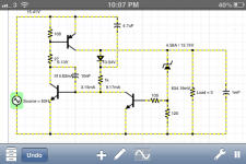
It's possible to build a discrete transistor regulator with only 3 transistors and a handful of other components that will vastly outperform any package regulator, with a full load dropout voltage equal to the saturation voltage of the pass transistor, (typically about 0.6v) better than 10mV line and load regulation, inherent short circuit protection, and good for about 5 amps.
I found this design in a magazine about 25 years ago (from memory Electronics Today International) and have used it many times in different applications, unfortunately I've lost the original article with the design equations, nor can I remember the authors name. Does anyone recognise it ?
I've attached a screenshot from a spice simulator - the resistor that says Load=3 is not part of the regulator but represents a dummy load. (The input "AC" is actually DC but with 50Hz ripple superimposed) Typically the PNP pass transistor would be a TO3 package, the NPN driving it a TO220, and the right most NPN a TO92 like a BC548. Output voltage is set by the zener diode.
Resistor values shown are not necessarily correct as I had just recently put the design into a spice simulator entirely from memory to play around with it.
3.4 amps from a TO220 sized regulator is also a bit optimistic IMHO, manufacturers spec sheet claims not withstanding.
It's possible to build a discrete transistor regulator with only 3 transistors and a handful of other components that will vastly outperform any package regulator, with a full load dropout voltage equal to the saturation voltage of the pass transistor, (typically about 0.6v) better than 10mV line and load regulation, inherent short circuit protection, and good for about 5 amps.
I found this design in a magazine about 25 years ago (from memory Electronics Today International) and have used it many times in different applications, unfortunately I've lost the original article with the design equations, nor can I remember the authors name. Does anyone recognise it ?
I've attached a screenshot from a spice simulator - the resistor that says Load=3 is not part of the regulator but represents a dummy load. (The input "AC" is actually DC but with 50Hz ripple superimposed) Typically the PNP pass transistor would be a TO3 package, the NPN driving it a TO220, and the right most NPN a TO92 like a BC548. Output voltage is set by the zener diode.
Resistor values shown are not necessarily correct as I had just recently put the design into a spice simulator entirely from memory to play around with it.
Attachments
Last edited:
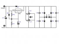
Attached is the schematic. Only imagine that there is another regulator (both LT1084) in parallel with the one in the schematic. It's IN and ADJ pins are common. Each one has it's own 0.22 Ohm resistor at each output that connects to the common point of D6, D7 and R10. Although when I did my measurements I had already yanked the regulator pair out and stuck in a simple LM317 as part of my trouble shooting.
The rectifier diodes are MUR410G (which I now see that I should be using something rated higher for current). Each diode has a 1000 pf film cap snubber. C11 and C12 are 10,000 uF at 16V (I added 4400 uF more during the test). C14 and C13 are 680uF at 16V. R10 is 124 Ohms and R11 is 499 Ohms.
The LT1083, LT1084 and LT1085 really are the very best of three pin adjustable regulators that I can find by far. If you know of any that are better then let me know. The LT1084 is low drop out and rated at 5A. They (LT) used to make an LT1083 in the metal TO3 can that was good for 7.5A but it is nearly unobtainable now and I am stuck with this topology due to the circuit board and the space in my DAC. I have decided to add a daughter board with a bunch of parallel 10,000 uF to supplement C12 and C11.
Attachments
Most 3 terminal regulators have very poor drop out voltage characteristics, typically 2 to 3 volts at full load, which also means quite high dissipation.
3.4 amps from a TO220 sized regulator is also a bit optimistic IMHO, manufacturers spec sheet claims not withstanding.
It's possible to build a discrete transistor regulator with only 3 transistors and a handful of other components that will vastly outperform any package regulator, with a full load dropout voltage equal to the saturation voltage of the pass transistor, (typically about 0.6v) better than 10mV line and load regulation, inherent short circuit protection, and good for about 5 amps.
I found this design in a magazine about 25 years ago (from memory Electronics Today International) and have used it many times in different applications, unfortunately I've lost the original article with the design equations, nor can I remember the authors name. Does anyone recognise it ?
I've attached a screenshot from a spice simulator - the resistor that says Load=3 is not part of the regulator but represents a dummy load. (The input "AC" is actually DC but with 50Hz ripple superimposed) Typically the PNP pass transistor would be a TO3 package, the NPN driving it a TO220, and the right most NPN a TO92 like a BC548. Output voltage is set by the zener diode.
Resistor values shown are not necessarily correct as I had just recently put the design into a spice simulator entirely from memory to play around with it.
Simon, Your schematic got me thinking. I remember now seeing a three terminal regulator composite circuit that used a pass transistor to increase the current capability. It must have been shown in a regulator's data sheet but I can't remember where for sure. A pass transistor would be great for a new design and it wouldn't take up that much more space. I have to believe that your schematic is really an oversimplified version of what is contained in modern three terminal devices.
The LT1084 is not a real LDO, it has 1V drop.
A better choice is the LT1581: LT1581 - 10A, Very Low Dropout Regulator - Linear Technology
It will be under 0.3V, and is good for 10A which means you can also get rid of the 0.22 ohm.
You could do better with a discrete regulator, but it would have to be MOS-based.
If you combine this VR with schottky diodes, or the synchronous rectifier, you should be OK
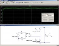
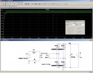
Here is a sim with your components, first with normal diodes: the voltage is clearly insufficient.
Then with schottky, you have a minimum of 7V, this requires a drop-out <0.7V.
With larger schottkys, you could have a margin of ~1V, sufficient for your LT1083 to regulate (without 0.22ohm)
Then with schottky, you have a minimum of 7V, this requires a drop-out <0.7V.
With larger schottkys, you could have a margin of ~1V, sufficient for your LT1083 to regulate (without 0.22ohm)
Attachments

With four parallel heaters? What happens when one fails? In addition, a current regulator will add the shunt voltage to the drop-out, definitely not a good idea IMHO.What about feeding Constant Current to the heater?
Build a CCS using your 3 terminal regulator.
- Status
- This old topic is closed. If you want to reopen this topic, contact a moderator using the "Report Post" button.
- Home
- Amplifiers
- Power Supplies
- 3 pin VR falls out of reg. way too early