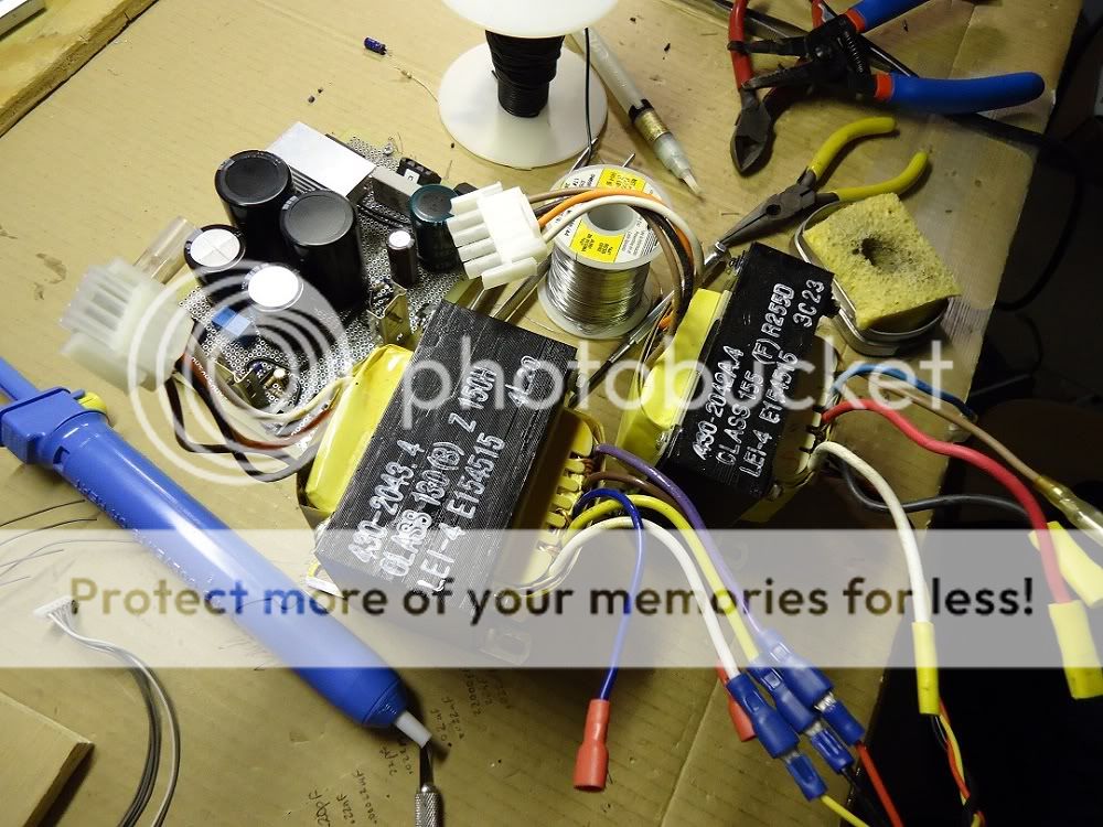
I got two of these transformers from an APC Uninterruptible PC power supply. I wondered if anyone might be able to tell me if they have any use for audio, or maybe a balanced power supply.
I will try to find any info there is out there, but from looking at others experiencies, it looks as thought these are custom made for the particular applliction.
It appears that the primaries were wired in series (white to white)
Further reading suggests that the BL & WH are the seconadries, probably wired in series to produce 48v?
I will try to find any info there is out there, but from looking at others experiencies, it looks as thought these are custom made for the particular applliction.
It appears that the primaries were wired in series (white to white)
An externally hosted image should be here but it was not working when we last tested it.
Further reading suggests that the BL & WH are the seconadries, probably wired in series to produce 48v?
Last edited:
The only thing that I ever had release smoke was one of those things. In fairness it was from a broken unit, so there could have been something wrong with it.
I just thought I would quickly wire it up in the shed to read some numbers. I think I put the juice to the black and white, it's been a while, the other leads were disconnected. Anyhow what ever I did, the transformer did not like it.
So ya, be sure you can sort out what is what before you power it up.") A bulb tester might be useful.
A bulb tester might be useful.
I just thought I would quickly wire it up in the shed to read some numbers. I think I put the juice to the black and white, it's been a while, the other leads were disconnected. Anyhow what ever I did, the transformer did not like it.
So ya, be sure you can sort out what is what before you power it up.
A bulb tester might be useful.I can't make heads or tails about what you are describing about the colors, from the picture it looks to me like one primary winding with B & W wires, and on the other side of the transformer there are two secondaries with (can't tell for sure, reddish hued pic plus discolored sleeves...) green - yellow, and white - black wires.
primaries vs secondaries... this might have 12V or 24V rated primary winding for power input from the battery, and a secondary winding producing 110V to 220VAC from a 50Hz switcher circuit, plus the 2nd, secondary winding producing a lower voltage level for the logic and control circuit. "IF" that is the case, it's not very useful for most audio projects though possibly it could be part of an overkill-built PSU for a ~ 15W/channel amp if the winding ratio is right for 24V output from one side with mains AC voltage input from the other side (considering the original primary to now be the secondary and vice-versa). Make sure no windings are connected to the core, are fully isolated.
primaries vs secondaries... this might have 12V or 24V rated primary winding for power input from the battery, and a secondary winding producing 110V to 220VAC from a 50Hz switcher circuit, plus the 2nd, secondary winding producing a lower voltage level for the logic and control circuit. "IF" that is the case, it's not very useful for most audio projects though possibly it could be part of an overkill-built PSU for a ~ 15W/channel amp if the winding ratio is right for 24V output from one side with mains AC voltage input from the other side (considering the original primary to now be the secondary and vice-versa). Make sure no windings are connected to the core, are fully isolated.
Last edited:
find out how many different windings there are. Label them
Measure the resistance of each winding and any additional taps that some/none of the windings have.
Assume the highest resistance winding is the primary of a step down transformer.
Test the primary through a bulb tester.
Measure the open circuit voltages of all of the windings.
Decide from the numbers if it really was a step down transformer intended for operation at mains voltage.
BTW,
the bulb tester will prevent you blowing up the transformer, even if it was never intended for mains operation.
Ive got a couple of those myself, and use them as part of my test rig when building an amp (or whatever).
All I know for sure is on these the brown and white wires (on the far ends of the white connector) are the primary.
Both have a center tapped secondary (white/purple with yellow as CT on one, and white/black/red (dont remember which is who off the top of my head) on the other).
Youre correct about them being custom for the APC UPS application, and if youre ever able to locate any specific info on it I would be very interested in your source.
The reference designation that begins with E followed by 6 digits (E123456) is ACP's Underwriters Laboratories file number, but I havent been able to make sense of the other designations.
I know thats not a lot of help, but you should be able to use it for any number of things if you can figure out the winding's on yours.
Edit: Meant to add the picture!
Last edited:
posted this in another thread:
verify coils(which color wire goes with what other wire/s) and resistances using dmm...
the coil with the lowest resistance would be the low voltage coil...
you can inject 6 to 12 volts into that coil....
measure all voltage across other coils and record them on a sheet of paper so you can look at it later...
you can try to confirm phasing of the coils by conecting coils in series, (make sure the traffo under consideration is not energized). record the connection on your paper...
try reversing the connections until you can veify that voltages are increasing with series connection and not decreasing...
armed with these information, you can then decide how the final connection of your traffo is going to be....
hope this helps....
- Status
- This old topic is closed. If you want to reopen this topic, contact a moderator using the "Report Post" button.
- Home
- Amplifiers
- Power Supplies
- Transformer