I will throw my $0.02 into the ring. For an AC mains transformer that is peak rectified, the conduction angle for the point at which the rectification occurs moves down as you load the transformer. The flat-top may well be the surge current into the bulk capacitors following the rectifier. Unfortunately the product of AC Mains rectification and achieving low ripple means that you end up with a lot of capacitance following the rectifier. This means you have a very low parallel ESR for the capacitors and that your peak current into the capacitor as you load your circuit up will increase rather dramatically as the conduction angle opens up.
Though the transformer is rated for a certain load, that rating is usually done with a resistive load and not a rectified load. The reason is that they do not know you much capacitance you will add.
If you have a current probe see if the flat top occurs co-incident with the peak of the current into the rectifier. I will be willing to bet this is your issue.
If you don't have a current probe, take out half your output capacitance and see if the flat top moves.
I suspect that what you will find is exactly what you surmised in you opening post where you ask about the saturating core.
Don't know for sure if I am correct, just my opinion. Take it for what it costs you.
Tony
I contacted my power provider yesterday, and they were genuinely interested in my case, well, at least one of the engineers was. He told me they could to a week long measurement, but if my power quality is within the norm they would have to charge me for the measurement (around 150Eurs). I sent him a pic of the waveform today, we'll see what he responds.
Here the mains voltage is regulated by the EN50160 norm, and therein it's stated that the THD must not exceed 8%. I guess I might just be below that.
dtproff, thanks for your input. Look at the 2nd pic in my first post. That waveform was taken directly from a lamp socket, straight off the circuit breaker so to say. At the moment I don't have any equipment with any large capacitance connected (DCB1 preamp, LM4780 gainclone, Laptop, fridge, lighting), so I think that's not the culprit.
I think I should measure during the weekend, if any commercial units are causing this they may be off the grid at that time...
I found an additional thread with a similar problem: Mysterious Power Line Super Gremlins
Rodeodave;
Sorry I missed that picture. I have seen some pretty ratty looking waveforms in office and apartment buildings. Those were usually the result of highly inductive loads bein a long ways from the mains transformer. Typically the air conditioning and elevators were the culprit (especially the VFD motors). But I haven't seen a waveform off the grid like yours.
Let us know the results... I'm curious now.
Tony
Okay, so I sent additional pics to the engineering guy. He seemed like a nice guy over the phone, let's hope he replies...
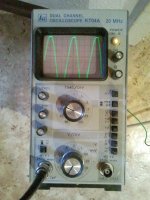
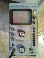
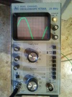
These pics were taken directly off the hot contact of an outlet. Probe was set to 10-fold attenuation, 10V per div, so that makes 100V per unit on the screen. Coupling was DC, and the scope works fine. Too bad the whole waveform doesn't fit on the screen. RMS voltage was 232,5V at the time of measurement.
These pics were taken directly off the hot contact of an outlet. Probe was set to 10-fold attenuation, 10V per div, so that makes 100V per unit on the screen. Coupling was DC, and the scope works fine. Too bad the whole waveform doesn't fit on the screen. RMS voltage was 232,5V at the time of measurement.
Attachments
")
You could put a mains filter on the front of anything that might take offence to harmonics.
Hey, this is emi filter, this does not do anything to harmonics.
Rodeodave,
post #2 and post #6 are telling the whole story. One minor thing was not explicitly stated. Mains line impedance. The flat top on the mains voltage is a byproduct of a number of peak rectifiers all drawing current in sync with the peak of the common mains voltage waveform. The non linear current peaks together with non zero line impedance are causing a voltage drop and consequently a distorted mains voltage.
There is no practical EMI filter to fix what is a low frequency (line harmonics) effect. The typical solution to this issue is the adoption of PFC rectifiers instead of peak rectifiers. PFC supplies are mandatory for PC and TV sets with very low input power limits (50W IIRC), also they are mandatory for equipments in the 75W to 1KW range for residential installations. This is enforced by the EN 61000-3-2 standard since a decade, at least.
IIRC, mains voltage THD should be <3%, not 8% (but I may be wrong, I'm not in the office now and I cannot check the standards).
Just my 0.02$
Scope is not clipping, the waveform looks the same on the secondary of a 15VAC transformer. Plus the probe is attenuating 10-fold.
EN50160 allows for 8% THD, see here for example: http://www.evu-messtechnik.de/docs/EVU-DIN_EN_50160-i.pdf. The individual harmonics must not exceed 5% for 3rd, 6% for 5th, 5% 7th and so on.
Meanwhile the engineering guy replied, and he offered to get a measurement done at the house connection, with the power company covering the costs. This shall be interesting.
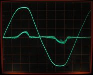
Here's what the mains look like in a residential area outside Raleigh, NC, USA. The larger trace is from Line to Ground, at 50V/div. The smaller trace is from Neutral to Ground, at 1V/div. This second trace is showing the voltage drop on the neutral line from where it is bonded at the distribution panel, to this outlet, which effectively represents the current on this branch circuit.
The loads are a 1000VA UPS serving one PC and the usual peripherals, a small studio amp playing music at low level, a 20W fluorescent light fixture with electronic ballast, and the scope itself.
I doubt that flattened peaks are all that unusual, for the reasons already explained.
The loads are a 1000VA UPS serving one PC and the usual peripherals, a small studio amp playing music at low level, a 20W fluorescent light fixture with electronic ballast, and the scope itself.
I doubt that flattened peaks are all that unusual, for the reasons already explained.
Attachments
I don't know that there is much they will (can) do for you. As has been explained (and partially ignored), this flat topping is typical, and not at all abnormal in today's electronic world without power factor correction (electronic control system that forces current draw as a sine wave).
At best, they could install a larger transformer to reduce the source impedance. Voltage drop across impedance at the peak current is the root cause. This is a result of ohm's law. You don't filter it out; there is no defective equipment. It is expected.
A larger transformer will still exhibit some flat-topping, just less extreme.
- Status
- This old topic is closed. If you want to reopen this topic, contact a moderator using the "Report Post" button.
- Home
- Amplifiers
- Power Supplies
- How bad is the quality of my mains voltage and what can I do to improve it?