I have re-built a power supply to power some bridged GCs that I built, tested and never used. Basically it is to tidy things up so that I could safely use the amps.
The Trannys are 300va 25 + 25 AC. I was using Carlos Filipe's schematic for the original rectifiers and seem to remember that each rail was around 42 - 45vdc (just within the 3886 limit)
To tidy things up I have used some generic rectifier boards. The resistors are 2.2k between rails and 1R elsewhere. There are 2 R1's on each rail (one under the board on each side)
I am getting roughly 51vdc after rectification which is too high. I asssume that I could reduce this by changing the resistor values. Am I correct?
An externally hosted image should be here but it was not working when we last tested it.
An externally hosted image should be here but it was not working when we last tested it.
These are the trannys I am using :-
CLAIRTRONIC|12082|TRANSFORMER, 300VA 2X 25V | Farnell United Kingdom
I have measured both and the secondarys are 38vac! I am not sure what is going on. It is so long since I used them that I assume they must have measured correctly on receipt.
CLAIRTRONIC|12082|TRANSFORMER, 300VA 2X 25V | Farnell United Kingdom
I have measured both and the secondarys are 38vac! I am not sure what is going on. It is so long since I used them that I assume they must have measured correctly on receipt.
Im also thinking you have a 35-0-35 trafo. Do you have the primarys wired corectly
Primaries are fine.
Primary wiring (details on side of tranny) Blue, Grey, Violet, Brown. Blue and Grey one pair, Vio and Br 2nd pair. For 240v you join Grey and Violet.
Dual primaries should show ~240Vac across the series pair.
Then show ~120Vac across each single primary.
Bulb not lighting, or do you mean when checking the primaries as above? I am not clear as to how you are suggesting I measure.
Dual primaries should show ~240Vac across the series pair.
Then show ~120Vac across each single primary.
Bulb not lighting, or do you mean when checking the primaries as above? I am not clear as to how you are suggesting I measure.
with dual primaries all four ends are available to measure voltages.
measure across one primary winding.
Now measure across the other primary winding.
Now measure across the series pair of primary windings.
You should see readings of ~120Vac, ~120Vac, ~240Vac.
The bulb off indicates you have not wired the primaries out of phase.
measure across one primary winding.
Now measure across the other primary winding.
Now measure across the series pair of primary windings.
You should see readings of ~120Vac, ~120Vac, ~240Vac.
The bulb off indicates you have not wired the primaries out of phase.
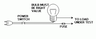
Bulb tester
Hi Puffin,
I guess this is what AndrewT suggest to you
Make sure the load is greater VA than the bulb...
Do you use 1 or 2 trafo for this GC?
If you try to use 2 trafo & it is 2x25 Vac
then if you connect it like the schematic it will be 2x50 Vac because maybe you not use the ct of the trafo...
btw have you measure the secondary, it is 25 ct 25 right?
On the schematic that use 2 trafo & single 22-24 Vac
if your trafo has dual secondary eg 0-25 & 0-25, why not build dual mono amp
Regards
Attachments
Last edited:
John. Each tranny has dual seconarys. The centre pair are joined to make them CT. When the ac secondarys are tested they are showing 35vac.
Andrew T is suggesting I check that I have the primaries correctly wired. I will do this today.
I have been using a light bulb tester for many years.
Regards
Rob.
Andrew T is suggesting I check that I have the primaries correctly wired. I will do this today.
I have been using a light bulb tester for many years.
Regards
Rob.
If dual primaries are wired correctly the bulb will stay off if nothing else is connected to the transformer DUT.The bulb off indicates you have not wired the primaries out of phase.
If the primaries are paralleled and out of phase, the bulb will light full bright.
If the primaries are seriesed and out of phase, the bulb will light full bright.
That's why I keep reminding Members to always use the bulb for mains testing.
Hi AndrewT, good suggestion I also must remind itmeasure across one primary winding.
Now measure across the other primary winding.
Now measure across the series pair of primary windings.
You should see readings of ~120Vac, ~120Vac, ~240Vac.
")
I know AndrewT suggest this to ensure that trafo is normal at primary
Blue and Grey one pair --- measure here should be 120Vac
Vio and Br 2nd pair --- measure here should be 120Vac too
Blue and Br --- measure here should be 240Vac
If the reading 120Vac is not same than your primary must be damage
I will suggest you the reverse way if you have another trafo that is normal & output 0-25 volt. Connect it to one of the secondary of your trafo & measure all another primary & secondary.
If you find that one of them not similar....
your trafo is really in big troubleFor more on light bulb testers, see:
http://www.diyaudio.com/forums/power-supplies/167579-light-bulb-tester.html
http://www.diyaudio.com/forums/power-supplies/167579-light-bulb-tester.html
with dual primaries all four ends are available to measure voltages.
measure across one primary winding.
Now measure across the other primary winding.
Now measure across the series pair of primary windings.
You should see readings of ~120Vac, ~120Vac, ~240Vac.
The bulb off indicates you have not wired the primaries out of phase.
I have been doing a bit of head scratching about this. I have definitely got the primaries wired correctly for 240v (Grey & Vio joined) Br & Bl connected to 240v. Would I be riight in assuming that I should connect one set of primaries (Bl & Gr) to 240v and then measure the other pair (Vio & Br ) and then vice versa (each pair should measure 120v)?
- Status
- This old topic is closed. If you want to reopen this topic, contact a moderator using the "Report Post" button.
- Home
- Amplifiers
- Power Supplies
- GC Split Rail Supply