Over the past few weeks I've spent part of my free time designing a simple voltage regulator. I've posted during the design process in a different forum, but now that the design is mostly complete I'd like to post it here and share it with the members of this forum as well.
I'll start by saying that the purpose of the design was to build something of my own from start to finish. It started with an idea (a voltage regulator of above average performance - better than LM317 and similar, fully discrete, which wont use the common zener->differential amplifier combo), through the initial design + simulations using pSpice, prototyping, and generating Gerbers and sending them over to be manufactured.
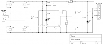
The PCB's have returned a while back, and I did some more testing and measurements. I will first post the schematic, and then some details about performance:
The circuit is very simple, M2 is the pass transistor, J1 is used as a CCS fed by a LPF, and M1 is operated in a CS configuration. Any change in the output voltage changes M1's VGS which is then amplified by M1 and used to change the gate voltage of M2. I did some measurement with a better CCS (cascode current mirror for example), and a cascode transistor above M1, but it had negligible effect on performance so I left these out to keep the dropout voltage of the regulator acceptable.
I've measured the output noise using tangents LNMP -> Agilent U1253A (BW of the LNMP is about 5Hz->100KHz). For an output voltage of 24V the output noise is 12uVrms under no load, and ~90uV with a 30ohm load (~0.8A). With the output voltage set to 3.3V the noise with no load is about 5uVrms.
I've also measured the voltage drop at the moment the 30ohm load is connected, and it dropped by about 10mV at the moment the connection was made (this is with a 24VDC output voltage so the current changes from 0A -> 0.8A), which means the high frequency output impedance is relatively low (10mV/0.8A = about 13mohm).
The current limiting is adjustable using Rsense, and I've measured for a few currents starting from about 0.4A up to about 2.5A and it performed as expected, so I'm quite please with it. It doesn't have foldback, so CSLED can be used to inform the user the current limiting is activated to avoid damaging the pass transistor in case of a short circuit down the chain.
After receiving the boards and testing the current limiting I've revised the PCB layout and changed a couple of footprints + included the current limiting on-board (the first PCB version didn't have this feature, and the current limiting was built on a proto-board and soldered to the main regulator board). I've also added an optional spot for a trimpot in series with Ra to allow compensating for the Vth spread of the transistor (M1) to set the output voltage with greater accuracy (as you'd expect it still isn't as stable with temp. as a band-gap + diff amp - but I can live with than") ).
).
Overall this is a very simple design which performs quite good. I'm happy with the way it turned out, and I already have a couple of these running for the last few weeks. If anyone will be interested I can post the BOM as well (just have to organize it in a PDF file). I haven't sent the new Gerbers to be manufactured, but if there are people interested in a PCB I'll happily do so. The boards are about 5cmX10cm, so iTeadStudio and the like will fabricate them for a few $ each.
I'll start by saying that the purpose of the design was to build something of my own from start to finish. It started with an idea (a voltage regulator of above average performance - better than LM317 and similar, fully discrete, which wont use the common zener->differential amplifier combo), through the initial design + simulations using pSpice, prototyping, and generating Gerbers and sending them over to be manufactured.
The PCB's have returned a while back, and I did some more testing and measurements. I will first post the schematic, and then some details about performance:
An externally hosted image should be here but it was not working when we last tested it.
The circuit is very simple, M2 is the pass transistor, J1 is used as a CCS fed by a LPF, and M1 is operated in a CS configuration. Any change in the output voltage changes M1's VGS which is then amplified by M1 and used to change the gate voltage of M2. I did some measurement with a better CCS (cascode current mirror for example), and a cascode transistor above M1, but it had negligible effect on performance so I left these out to keep the dropout voltage of the regulator acceptable.
I've measured the output noise using tangents LNMP -> Agilent U1253A (BW of the LNMP is about 5Hz->100KHz). For an output voltage of 24V the output noise is 12uVrms under no load, and ~90uV with a 30ohm load (~0.8A). With the output voltage set to 3.3V the noise with no load is about 5uVrms.
I've also measured the voltage drop at the moment the 30ohm load is connected, and it dropped by about 10mV at the moment the connection was made (this is with a 24VDC output voltage so the current changes from 0A -> 0.8A), which means the high frequency output impedance is relatively low (10mV/0.8A = about 13mohm).
The current limiting is adjustable using Rsense, and I've measured for a few currents starting from about 0.4A up to about 2.5A and it performed as expected, so I'm quite please with it. It doesn't have foldback, so CSLED can be used to inform the user the current limiting is activated to avoid damaging the pass transistor in case of a short circuit down the chain.
After receiving the boards and testing the current limiting I've revised the PCB layout and changed a couple of footprints + included the current limiting on-board (the first PCB version didn't have this feature, and the current limiting was built on a proto-board and soldered to the main regulator board). I've also added an optional spot for a trimpot in series with Ra to allow compensating for the Vth spread of the transistor (M1) to set the output voltage with greater accuracy (as you'd expect it still isn't as stable with temp. as a band-gap + diff amp - but I can live with than
).Overall this is a very simple design which performs quite good. I'm happy with the way it turned out, and I already have a couple of these running for the last few weeks. If anyone will be interested I can post the BOM as well (just have to organize it in a PDF file). I haven't sent the new Gerbers to be manufactured, but if there are people interested in a PCB I'll happily do so. The boards are about 5cmX10cm, so iTeadStudio and the like will fabricate them for a few $ each.