Working on my toobscoap, I have two long tailed pairs, supplied by MOSFET CCSs. Since the supply is regulated, I don't have any problem with using a voltage divider to set the gate voltage.
Testing with an X-Y pattern and scoping the deflection voltages, I noticed an odd artifact on the deflection plate voltages: when the horizontal sweep resets, there's a hump on the vertical waveform. It's common mode, so I don't see it anywhere on the CRT.
Poking in a bypass capacitor appropriately, it goes away.
So just a warning: 1. It doesn't really matter if the gate bias supply is bypassed, because common mode signals are well attenuated by full differential circuitry (like oscilloscopes and push-pull amplifiers). The only problem is it's inelegant, so 2. put in a teeny bypass cap just in case.
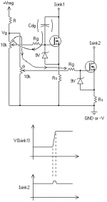
For visual, see attached. The bypass cap, of course, goes from "Vg" to ground, and 0.1uF is probably more than enough in any case. Many times, a regulated voltage is not available and a zener diode is used to fix this gate reference voltage; this works well, but a particularly fast downward transient will still couple through. A capacitor will also reduce HF noise from the zener.
I don't know how many people use common-reference CCSs. This is by no means an indictment against such usage, merely a warning to keep it clean. Reusing the reference will save supply current, zener diodes, heat and keep all your CCSs closer together over time and temperature drift.
Tim
Testing with an X-Y pattern and scoping the deflection voltages, I noticed an odd artifact on the deflection plate voltages: when the horizontal sweep resets, there's a hump on the vertical waveform. It's common mode, so I don't see it anywhere on the CRT.
Poking in a bypass capacitor appropriately, it goes away.
So just a warning: 1. It doesn't really matter if the gate bias supply is bypassed, because common mode signals are well attenuated by full differential circuitry (like oscilloscopes and push-pull amplifiers). The only problem is it's inelegant, so 2. put in a teeny bypass cap just in case.
For visual, see attached. The bypass cap, of course, goes from "Vg" to ground, and 0.1uF is probably more than enough in any case. Many times, a regulated voltage is not available and a zener diode is used to fix this gate reference voltage; this works well, but a particularly fast downward transient will still couple through. A capacitor will also reduce HF noise from the zener.
I don't know how many people use common-reference CCSs. This is by no means an indictment against such usage, merely a warning to keep it clean. Reusing the reference will save supply current, zener diodes, heat and keep all your CCSs closer together over time and temperature drift.
Tim
Attachments
")
D.Self run into a slightly different problem.
He linked the two CCSs feeding the LTP & VAS. He could not stop them interacting.
He finished and printed 2nd edition without a solution. 4th edition has the same error. I wonder if 5th edition is any better?
I see many copying the multiple CCSs from one voltage source. It looks wrong, now you are showing why it is wrong.
Hardly wrong, I've demonstrated why it's fine -- MOSFETs couple capacitively; load it with more capacitance and it's fine.
BJTs are a slightly different story, though the trick can be used intentionally to save bias current in some cases. Take this circuit for instance:
Not as much application in audio for this, except perhaps limiting / clipping protection circuitry.
Tim
BJTs are a slightly different story, though the trick can be used intentionally to save bias current in some cases. Take this circuit for instance:
An externally hosted image should be here but it was not working when we last tested it.
Not as much application in audio for this, except perhaps limiting / clipping protection circuitry.
Tim
http://www.diyaudio.com/forums/atta...1d1327376078t-ccs-sharing-warning-ccs_cap.png
I interpret the diagram you have posted as showing a reaction in the non changing channel (sink I2) when a change occurs in the operating channel (sink I1).
That surely is an example of what should not happen. To me you have demonstrated why it is wrong.
How does one repeat a pic from an earlier post?
Last edited:
- Status
- This old topic is closed. If you want to reopen this topic, contact a moderator using the "Report Post" button.