45vdc and 3v warm white led? Okay.
10 series led series to 1.2k resistor, or
11 series led series to 1k resistor, or
12 series led series to 820 ohm resistor, or
13 series led series to 470 ohm resistor, or
14 series led series to 270 ohm resistor, or
(93% efficient) 14 series led series to 3 series power diode series to 68 ohm resistor, or
(97% efficient) 14 series warm white led series to 1 50+ma amber led series to 68 ohm resistor
All of the above is 600ma (sum total of all parts running) same as the original fixture. There is approximately 13ma draw per led so that they need 32ma rating or greater, to ensure maximum longevity. Application matches with 8mm 1/2w warm white and 5050 and. . .
Economy solution:
Purchase 28 of 5mm flat top warm white 20ma or 25ma led.
Create parallel pairs for 14 of twin chip 33ma led.
Series 14 of 33ma led with 3 of power diode and 1 of 68 ohm resistor. If switch on voltage is not reached, subtract one or more of the power diodes to adjust trim.
Cost = 90 cents. Efficiency = 93% Derating and redundancy is excellent. Should 1 led quit, the rest stay lit. Can your driver chip do that? Probably not.
I can't understand what you have arrived at.
You started with 15 incandescent 1.9Lumen bulbs and you now require 10 1W 70Lumen LEDs to replace them?????
Yes, I too was wondering about the blindingly bright VU meters.
")
It is quite hard to make myself clear it seems.
There were 10 bulbs originally. I will use 20 white LEDs because they fit mechanically in the same space as 10 bulbs, so there will not be any visible bright spots where the LEDs are and shadows in between. The LED's will illuminate a diffuser and then the vu-meters. I will dim the LEDs in order to obtain the exact same brightness as before. I do not want a light show, but simply to recreate the exact same light as before.
The LEDs are these ones : LUMILEDS|LXHL-PW01|LED, LUXEON, EMITTER, LAMBERT | Farnell România
Thank you all again, and thank you KatieandDad for telling me the current trough the zenner is zero when mounted parallel with the load. I always assumed there will be some current flowing trough even with a load applied.
However is still need to use a driver for thermal compensation, your simple series resistor suggestions will not work.
But i can draw the PCB to accomodate both solutions, LM317HV and series resistor and zenner that feed the LED driver and just see which works best.
If you are going to take the 38VAC and rectify it, I think you can just use a regular LM317 to set the DC output to the LED driver.
Transformer secondary -> diode bridge -> 680uF electrolytic -> LM317 (w/ set resistors) -> 1uF tantalum -> TLE4242
It isn't clear whether the 38.2VAC is RMS or peak value.
BTW the zener current is zero only when the voltage across it is less than the breakdown voltage (disregarding any leakage). As explained, the goal is to have the vast majority of current flow on through the load.
[snip]Thank you all again, and thank you KatieandDad for telling me the current trough the zenner is zero when mounted parallel with the load. I always assumed there will be some current flowing trough even with a load applied.
[snip].
I think you are correct. If the current to the zener is zero you can remove it without any change. So either it is not required, or the current is not zero
jan
What about giving consideration to the earlier suggestion to use current drive. Drop the voltage driver idea completely and simply control the current with a CCS.
If your original lamps were 15 @ 1.9Lumens then look for 20 LEDs that can give a similar light output. Do not match the electrical power. Expect between 20Lumens/W to 120Lumens/W for white LEDs. Small low power white LEDs will probably be around the 20L to 40L/W
If your original lamps were 15 @ 1.9Lumens then look for 20 LEDs that can give a similar light output. Do not match the electrical power. Expect between 20Lumens/W to 120Lumens/W for white LEDs. Small low power white LEDs will probably be around the 20L to 40L/W
Why complicate things.
You know the current draw ~ 100mA
You know the voltage = 40V
Use 2 x 100R 0.5W resistors in parallel = 50R
And two 5W zeners in series 1N5355 (18V) + 1N5358 (22V) = 40V
There you have the simplest regulated supply that you can imagine.
You've mis-understood how a zener diode works.
If the voltage across the zener diode is LESS than the STATED VOLTAGE (ie 24V), then the zener diode will NOT conduct.
If the voltage across the zener diode is HIGHER than the STATED VOLTAGE the zener WILL conduct.
The outcome of placing a zener in series with a resistor is that the zener will conduct enough current through the resistor in such a way that the voltage across the zener will equal its stated voltage.
If the LOAD is drawing sufficient current to drop the neccessary voltage across the resistor then the zener will indeed do nothing.
The aim is to calculare the resistor value so that the load current plus about 5-10mA of diode current will flow through it.
You want to drop 5V with a load current of 100mA.
If we used a 50R resistor then the voltage across the zener would be at its rated voltage so no current would flow through the zener.
If we use a 45R resistor. Only 4.5V would theoretically be dropped across it due to the 100mA load. As the voltage across the zener is GREATER than its stated voltage - IT WILL CONDUCT. It will conduct about 10mA which will cause the voltage drop to be 5V as calculated.
The zener will reach a stable point at which the voltage across it will be equal to the stated voltage.
Zeners can be used in series so that odd values of regulated voltage can be produced.
The zener is quoted at 5W because it has to be capable of drawing the full 110mA if the load is disconnected.
If i use a simple series resistor i know it will work, but the LED's will work in a
high temperature environment besides the temperature generated by themselves
and they will begin to draw more and more current and shift brightness, causing
them to fail in time. I have seen this the first time in a LED version of the Maglite
torch and confirmed it when testing the white LEDs.
Hi,
You've lost me. A torch is a low impedance low voltage, voltage drive of the
LED, fair enough in that case the LED as it heats up will draw more current.
Running the LEDs from a high voltage rail via a resistor is current drive,
and the only thermal issue I can see is, if this is one resistor, one of
the LEDs might start to hog the current, runaway and eventually fail.
So use individual ballast resistors for each LED and one resistor to set
their dimness. If rail ripple / droop is to be eliminated then drive
the whole caboodle with from a series R parallel zener feed.
(Probably don't need a smoothing cap, but it won't hurt.)
Doesn't have to be 40V or 100mA, just have enough voltage
and current (110% no load, of the load) to do the job.
rgds, sreten.
rgds, sreten.
you know the total load current
It is quite hard to make myself clear it seems.
There were 10 bulbs originally. I will use 20 white LEDs because they fit mechanically in the same space as 10 bulbs, so there will not be any visible bright spots where the LEDs are and shadows in between. The LED's will illuminate a diffuser and then the vu-meters. I will dim the LEDs in order to obtain the exact same brightness as before. I do not want a light show, but simply to recreate the exact same light as before.
The LEDs are these ones : LUMILEDS|LXHL-PW01|LED, LUXEON, EMITTER, LAMBERT | Farnell România
Thank you all again, and thank you KatieandDad for telling me the current trough the zenner is zero when mounted parallel with the load. I always assumed there will be some current flowing trough even with a load applied.
However is still need to use a driver for thermal compensation, your simple series resistor suggestions will not work.
But i can draw the PCB to accomodate both solutions, LM317HV and series resistor and zenner that feed the LED driver and just see which works best.
Don't underestimate the brightness of those LEDs. A standard T-1 3/4 (5mm) white LED is really very bright - much brighter than you would expect if you are accustomed to standard old-school red or green LEDs. And they only draw a few mW of power each. The ones you are using are 1 W LEDs and will be astonishingly bright. Powered to full brightness it will be blindingly bright on your workbench... and you will have that times twenty. I would estimate you will need only a few mA of current through each LED to get the brightness that you want (making 1 W LEDs overkill to say the least, but if you already have them, you can certainly use them). You could string up 10 in series with a current limiting resistor, in parallel with another set of 10 just like the first. White LEDs have (roughly) 3 V of drop across them. With 10 x 3V of voltage drop in the LEDs, that's 30 V, you will have a few V, let's say 10 V of drop across the current-limiting resistor. Let's say you need maybe 5 mA of current. 5 mA x 10 V = 50 mW = 1/20 Watt. You can easily get away with standard sized 1/4 W or 1/2 W through-hole resistors. You can even increase the current substantially without worry about the resistor.
I agree with Macboy.
You do seem to be overcomplicating a VERY SIMPLE task.
For the sake of a few pennies, I would build a stripboard LM317 in CCS mode, not in your application but just as a test.
See how much current you need to pass through the LEDs in order to get the brightness that you need. THEN just use a series resistor to obtain that current in your application.
Last edited:
Hi,
Check this circuit. This is more or less what your are looking.
Here is the link An LED Array PWM Dimmer with the 555
Check this circuit. This is more or less what your are looking.
Here is the link An LED Array PWM Dimmer with the 555
I believe it is the duty cycle that is adjusted for brightness, not frequency (hence, Pulse Width Modulation). As far as "invisibility" goes, 100Hz or better will certainly be undetectable by the naked eye.
The 555 circuit seems pointless when discussing the TLE4242.
"...The voltage across the zener would be at its rated voltage so no current would flow through the zener" is the diode misunderstanding.
The 555 circuit seems pointless when discussing the TLE4242.
"...The voltage across the zener would be at its rated voltage so no current would flow through the zener" is the diode misunderstanding.
"...The voltage across the zener would be at its rated voltage so no current would flow through the zener" is the diode misunderstanding.
Sometimes we have to simplify a description to help those understand.
Attachments
A zener only STARTS to conduct once the voltage across it reaches its threshold voltage.
Below the threshold voltage the zener doesn't conduct.
It might pass a tiny leakage current but to all intents and purposes it is open circuit.
Zeners are prone to drifting but this is irrelevant in this threads application.
Below the threshold voltage the zener doesn't conduct.
It might pass a tiny leakage current but to all intents and purposes it is open circuit.
Zeners are prone to drifting but this is irrelevant in this threads application.
Last edited:
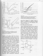
A Zener passes a little current when the applied voltage is at or below the marked voltage.
If you plot this current vs applied voltage you will see it rises from zero at zero volts to a value ~2% max current rating @ ~80% of the Zener marked voltage.
After that the I vs V plot curves around the knee to a new slope. This high voltage slope gives the dynamic impedance of the Zener. Small changes in applied voltage result in big changes in current on this high voltage slope. I normally recommend that the minimum Iz be 10% of max current rating if one wants to avoid the "knee" in the I vs V curve. But many Zeners can operate down to ~5% and still be just clear of the "knee".
Last edited:
If he wires the LEDs in series (as long as he hasn't got too many so that the voltage required to illuminate them is higher than the supply voltage), then the resistor will be a small commonly available resistor.
I haven't got the data available for the LEDs that he is thinking about using so this is just an example.
Lets say he wants to use 20 LEDs White ones that might take 3.1V and 20mA.
He can't use all 20 in series as that would need a supply of 20 x 3.1 = 62V.
Lets make two circuits - each with 10 LEDs.
Now the supply is 45V. 10 x 3.1V = 31V All he needs is to lose 14V @ 20mA
Simple Ohms Law, Resistor Required = Voltage / Current = 14/0.02 = 700 Ohms.
Not a common value so we use the next highest one available = 720 Ohms
POWER = I^2 x R = 0.02 x 0.02 x 720 = 0.3W
A common 720R 0.6W resistor in series with 10 x LEDs will be fine.
DO SUBSTITUTE THE CORRECT Vf and If FIGURES INTO THE EQUATIONS BEFORE BUYING YOUR RESISTORS.
There will not be much difference in the intensity with 5mA, 10mA or 20mA. If you want to dim the LEDs you will need to PWM them or put socks on them.
You think I jest. If they are too bright just cover them with something - paint is pretty opaque.
Last edited:
- Status
- This old topic is closed. If you want to reopen this topic, contact a moderator using the "Report Post" button.
- Home
- Amplifiers
- Power Supplies
- I need to drop about 5 Volt in an elegant manner