I'd like to know more about pop suppression on the mains switch of my power supply. Its for a gainclone type of chip amp, and when I turn it on or off, there is a "pop" sound from the speaker. I'd like to get rid of this.
I have some schematics for commercial amps, and these show a 10nF (0.01uF) X2 "safety" cap in parallel with the live wire switch contacts. I did some reading about snubbers for arc suppression, but was surprised to see commercial designs only using a single cap (which I assume is for suppressing the pop that I am hearing). Usually the manufacturers don't put in extra components that aren't needed, so I am guessing that the single X2 cap on the mains switch works.
I'd like to have this confirmed. I'd also like to know more about why this works for pop suppression, if anyone out there knows the answer (or thinks they do!).
Thanks,
-Charlie
The pop you are hearing is the inruch current into the capacitors when you first plg in. The eaiest method is to add a NTC thermistor inline with the AC mains. This will provide a relatively high (10-20 ohms) resistance when you first plug in and as the thermistor heats up from the current flowing though it, the resistance will decrease. Check teh current ratings on the device and read how to select teh correct value for your circuit and you should be good to go.
I hope my comments were helpful.
Tony
Tony
I hope my comments were helpful.
Tony
Tony
The cap is intended to extend the life of the switch. An RC network would be better than a straight C in my opinion.
A click at the point of switch-off may be an arc at the switch. The capacitor will stop this. For a cap bypassing the switch I think I would use something a bit smaller than 10nF, as this will let enough current pass to make you jump (although harmless). 10nF across the transformer primary is fine, and will have a similar effect.
A thump a few seconds later is the amp circuits switching off as the PSU caps lose charge. Similar thump at turn-on.
A thump a few seconds later is the amp circuits switching off as the PSU caps lose charge. Similar thump at turn-on.
Thanks for your replies.
What I am experiencing is a pop/snap sound at turn off. In multi-amp active speaker system, I also hear a pop (maybe through the other channels?) at turn on. I was operating under the assumption that this was RF generated by arcing across the switch contacts. Is that not right?
I am also planning to put a series RC network across the primary using 0.1uF X2 cap plus 1R 1W resistor. This reduces HF noise, no? Is the resistor sized correctly for that application?
I'm a little fuzzy how inruch current would cause these kind of noises. I am not hearing any "thump" at turn off BTW.
-Charlie
I have some schematics for commercial amps, and these show a 10nF (0.01uF) X2 "safety" cap in parallel with the live wire switch contacts. I did some reading about snubbers for arc suppression, but was surprised to see commercial designs only using a single cap (which I assume is for suppressing the pop that I am hearing). Usually the manufacturers don't put in extra components that aren't needed, so I am guessing that the single X2 cap on the mains switch works.
I'd like to have this confirmed. I'd also like to know more about why this works for pop suppression, if anyone out there knows the answer (or thinks they do!).
Thanks,
-Charlie
Yes, a 10nF or 4.7nF X2 Safety Cap or use High Voltage types (1,000~1,600Vdc).
Solder it across the power switch contacts. If it's double pole, use 2 caps, one for each pole. The caps will suppress the voltage spike when the contacts arc. Very effective. No need for RC snubber.
I am also planning to put a series RC network across the primary using 0.1uF X2 cap plus 1R 1W resistor. This reduces HF noise, no? Is the resistor sized correctly for that application?
Instead of an RC, you may want to install a MOV. This will prevent High Voltage Spikes on the Mains from passing through the power transformer.
A pop in other channels at turn-on is probably directly caused by momentary drop in mains voltage. Inrush limiting would reduce this.
Pop at turn-off could be RF, or could be a sudden rise in mains voltage. Maybe the other channels need better filtering?
You can sometimes get away without using a full snubber because the transformer primary resistance acts to damp the LC oscillation.
Pop at turn-off could be RF, or could be a sudden rise in mains voltage. Maybe the other channels need better filtering?
You can sometimes get away without using a full snubber because the transformer primary resistance acts to damp the LC oscillation.
I don't think that there is all that much inrush current. There is only 10,000 uF of caps in the PS, and the transformer is maybe 150VA.
Until recently, 'only 10,000uF' would be considered a largish cap.
4700uF per rail actually, so roughly 10,000 uF in total for the PS.
4700uF per rail actually, so roughly 10,000 uF in total for the PS.
Sorry, no. As there ist a cap each for the positive rail with respect to ground and for the negative rail, also with respect to ground, the caps are in series and the resultant capacity is ~2350 µF.
As for arc suppression snubbers: A 0.1 µF X class capacitor in series with a 100 ohms resistor would be fine. There are special caps with an in-built resistor available for this purpose.
Last edited:
Hi,
Just in case here is a link that explained your problem and how to solve it. The article is about how to built a snubber.
http://www.cde.com/catalogs/igbtAPPguide.pdf
regards,
tauro0221
Just in case here is a link that explained your problem and how to solve it. The article is about how to built a snubber.
http://www.cde.com/catalogs/igbtAPPguide.pdf
regards,
tauro0221
So far no one has answer the question about how and why the single cap across the switch works. Anyone?
Thanks for the link to the snubber design. That's for IGBT switchmode power supplies as far as I can tell.
-Charlie
Thanks for the link to the snubber design. That's for IGBT switchmode power supplies as far as I can tell.
-Charlie
When you break an inductive circuit (i.e. almost any piece of wire) the energy stored in the magnetic field has to go somewhere. Normally it goes into charging the capacitance across the gap. If very small (e.g. just a switch) then the capacitance is small so the voltage is very high, which leads to a spark. Putting a bigger capacitor reduces the voltage. If there is no spark to dissipate the energy then the LC circuit just oscillates for a while until the energy either gets radiated away (the circuit acts as a small antenna) or goes into heating up resistance in the circuit.
Sorry, I assumed people knew this.
Sorry, I assumed people knew this.
As DF96 says..
The idea is that any coil that has a magnetic field around it at power "Off"..the magnetic field collapses..This then cuts though the windings creating a back EMF (Voltage sometimes very high 1000V or more) this tries to conduct if the switch is opening the gap acts as a spark plug (like in your car) and the voltage causes a circuit to form as it arcs across the gap in the switch...as the switch gap gets bigger (opens to full gap) the arc is drawn wider until it cannot conduct any more or runs out of generated EMF and stops..
The cap across the switch acts as a temporary short (probably better to say it absorbs the energy) as the contacts open long enough for the gap to get to big for the arc to happen..
The comercial designs get away with this...its cheap...the answer is to stop the EMF at source using MOV protection and the cap...Why you may ask...well if the voltage from the EMF is higher than your transformer insulation can take, it will arc between the windings and stuff it..Also the switch can weld closed with inrush current so surge protection can reduce the inital current flow as the caps charge on power up..so you have to protect on power on and off...
Regards
M. Gregg
Last edited:
A BIG THANK YOU to DF96 and M Gregg for the explanation. I should have mentioned that I am an engineer, so I can't sleep unless I know *why* something is happening...
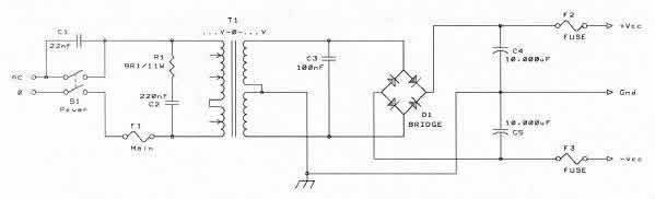
With that said, to further my understanding, the circuit shown below has both the cap across the switch and a snubber across the transformer primary. Is the cap on switch taking care of turn off transient from the collapsing magnetic field and the snubber is damping turn-on transients? I'm not clear on the snubber now... See image, below:
-Charlie
No need for RC snubber.
It is necessary. Top of page 3.
http://relays.te.com/appnotes/app_pdfs/13c3236.pdf
A BIG THANK YOU to DF96 and M Gregg for the explanation. I should have mentioned that I am an engineer, so I can't sleep unless I know *why* something is happening...
With that said, to further my understanding, the circuit shown below has both the cap across the switch and a snubber across the transformer primary. Is the cap on switch taking care of turn off transient from the collapsing magnetic field and the snubber is damping turn-on transients? I'm not clear on the snubber now... See image, below:
-Charlie
The snubber across the primary is trying to give a circuit (a path for it to take) for the EMF transient at switch OFF... remember the cap is only protecting the switch contacts from the arc....the high voltage at switch off is still there...and it will damage anything connected to it if it exceeds the insulation rating...A metal oxide varisor (MOV) is better...remember what is true for the primary is also true for the secondary..IE the transient caused by the collapse of the magnetic field also cuts through the secondary winding...
Your circuit does not show any inrush protection...you would need some kind of series resistance in the mains to the Tx primary..
Inrush Current FAQ - Ametherm
Now just to get you thinking... what is going to happen to the diode rectifier if it gets a transient higher voltage than the rating of the diode?
Think transformer...if the voltage in on the primary is high what happens to the secondary votage? If you don't control the voltage on the primary side (protect from transient) the transformer will reflect this in the secondary..
Regards
M. Gregg
- Status
- Not open for further replies.
- Home
- Amplifiers
- Power Supplies
- arcing mains switch -> add cap in parallel -> WHY?