Hi
I am trying to put together an amp that requires a 25-0-25 VAC transformer, one per channel. I have two 30.6-0-30.6 VAC transformers I acquired a while back, and would like to use these if possible as I am trying to keep this build to the minimum.
Can I unwind the transformer until I achieve the correct voltage?
Many thanks
That depends entirely on how it's wound. The answer is yes, if you can do it. You need to unwind the same amount of both secondaries. Sometimes primary and secondary wires are wound on together (with more prmary wires than secondary, then the primaries are put in series after it's all wound). Other times they are in layers, in which case you'd have to unwind layers to get to the previious winding. Good luck.
I wound a transformer for a valve amp years ago, and the secondary voltage was proportional to the number of windings. So, yes, in theory, but can you unwind without it all coming loose? I must add that I am no expert.
30.6Vac transformer?
Is that stated on the label?
or
did you measure the unloaded output voltage?
I suspect you have a 25Vac or 28Vac transformer, not a 30.6Vac transformer.
Is that stated on the label?
or
did you measure the unloaded output voltage?
I suspect you have a 25Vac or 28Vac transformer, not a 30.6Vac transformer.
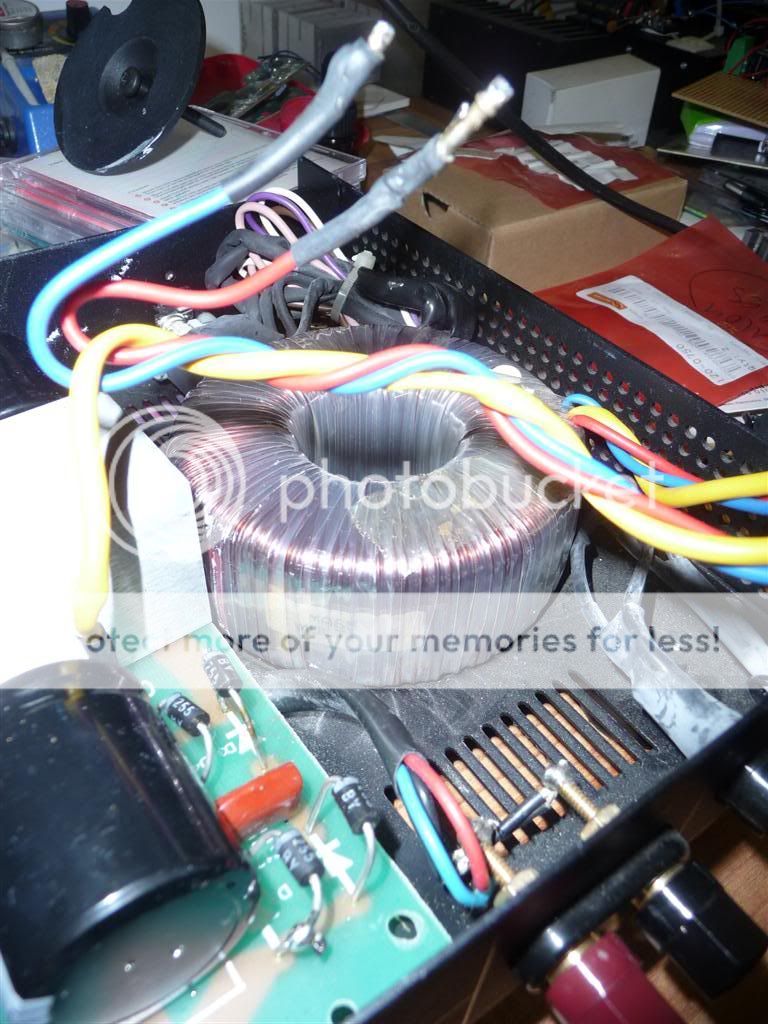
From the looks of the picture I think you have both secondaries winded simultaneously. You need to unwind that type of transformer without removing the cores, like threading the wire.
How many turns? Measure the voltage before and after you take 10 out to figure out how many turns per volt you have.
How many turns? Measure the voltage before and after you take 10 out to figure out how many turns per volt you have.
You can easily add windings! Use a similar gauge wire and wind on two pieces at a time. i suspect you will need about 15 to 20 turns. That should give you 5 volts which when wired out of phase with the existing windings will drop you to 25 volts!
Or just keep winding and make your own secondaries at 25 volts!
Or just keep winding and make your own secondaries at 25 volts!
Hi
Thank you for all of your replies.
I'll answer Andrew's question.
The transformers were taken from a MF MA65 power amp. I Googled the transformer model number but could not find anything online.
http://www.ilpelectronics.com/images/pics/transformers_mains.pdf
Judging by the dimensions it appears to be a 120VA 30-0-30 transformer
Diameter 95mm (A) x 45mm (B)
I measured the voltage from the transformers output whilst disconnected from the PCB. This gave a reading of 30.6VAC. If you take a look at the PDF they made a 30+30 transformer.
I'm trying to cobble together a couple of MyRefC mono blocks without spending too much money. The preferred transformer is 25-0-25 or slightly less if used with a 4 ohm load.
I hope this helps
Regards
Last edited:
It may be simpler to use a bucking transformer to reduce the input voltage - that way, you wouldn't need to touch the main transformer. ~20V of bucking would get you what you need.
Last edited:
You can easily add windings! Use a similar gauge wire and wind on two pieces at a time. i suspect you will need about 15 to 20 turns. That should give you 5 volts which when wired out of phase with the existing windings will drop you to 25 volts!
Or just keep winding and make your own secondaries at 25 volts!
Sounds good. I'm intrigued by the way transformers operate. The more I hear...
It may be simpler to use a bucking transformer to reduce the input voltage - tat way, you wouldn't need to touch the main transformer. ~20V of bucking would get you what you need.
Hi Wrenchone
Will check out the cost of these. Transformers are not that expensive, just under £30 each if ordered separately inc. postage and vat. If the bucking transformers are cheap enough it may be viable.
Regards
Simon's approach of adding bucking windings to the transformer to be placed in series with the secondary will also work. This can be done without butchering the original transformer. Add some tape around the extra windings, so that the transformer mounting washer doesn't savage them. You will need two windings for this purpose - wind them simultaneously (bifilar). BTW, any transformer can be a bucking transformer - it's the way you use it that matters. The secondary rating of the transformer used for bucking should be similar to the primary current draw of the transformer that you're bucking.
Last edited:
Using a buck transformer, or a buck connected winding, reduces the performance of the transformer.
Most of this loss of performance is due to the increased resistance of the windings.
Most of this loss of performance is due to the increased resistance of the windings.
Using a buck transformer, or a buck connected winding, reduces the performance of the transformer.
Most of this loss of performance is due to the increased resistance of the windings.[/QUOTE
Is the loss in performance significant?
yes,
~2/3rds of the transformer regulation is due to resistance.
If you have a 25Vac 160VA transformer, you have a certain resistance and regulation.
Now use a 30Vac 160VA transformer with a 5Vac buck winding with the same current capacity. You have 25Vac coming out of the resistance of a 35Vac winding. You have increased the resistance by about 40%.
That 2/3rds has increased by almost a 1/3rd. The total regulation increases by ~20 to 30%. That is a very significant loss of performance. These were not calculated. All of this is based on guesstimates. I suspect I have under-estimated the increase in regulation, But I'd suggest it may be equivalent to choosing a 80VA to 100VA transformer instead of a 160VA
Simply removing 5Vac of secondary winding from a 30Vac transformer also reduces the effective VA, but does so much more efficiently, since that reduces the resistance.
The 30Vac 160VA goes down to ~25Vac 133VA
Build up your PSU. Attach a dummy load that draws the typical quiescent current of the amplifiers you intend to use.
Measure the actual mains and PSU voltages.
The 30Vac 160VA goes down to ~25Vac 133VA
Build up your PSU. Attach a dummy load that draws the typical quiescent current of the amplifiers you intend to use.
Measure the actual mains and PSU voltages.
Last edited:
You can easily add windings! Use a similar gauge wire and wind on two pieces at a time. i suspect you will need about 15 to 20 turns. That should give you 5 volts which when wired out of phase with the existing windings will drop you to 25 volts!
Or just keep winding and make your own secondaries at 25 volts!
this is a good plan, your torroid can take this.............temporarily wind a ten turn winding to get the turns per volt, then knowing that multiply by 5 to get the exact number of turns, then take it out..........you will need 2 coils to connect at each end out of phase to get 25v..........use the same wire size for the additional coils.......very doable.....
this is a good plan, your torroid can take this.............temporarily wind a ten turn winding to get the turns per volt, then knowing that multiply by 5 to get the exact number of turns, then take it out..........you will need 2 coils to connect at each end out of phase to get 25v..........use the same wire size for the additional coils.......very doable.....
Thanks Tony
I will see if I can find the actual VAC figure from the manufacturer and if I have enough to play with after loss I will give this a go. What are your thoughts regarding loss of efficiency?
I found your transformer winding thread interesting BTW.
Regards
The VA or power rating is determined by the size of the core. The primary needs to have enough windings to make sure that the core does not saturate. The secondary windings on a toroid will couple well, that means the voltage sag from unloaded to full load will be low, most often less than 5%. That loss is mostly due to the gauge of the primary winding.
If you know the current draw from your load and are using diodes and capacitors to get the dc supply the peak current will be less than four times the average, based on measurements of similar circuits. As wire ratings are based on failure that means a wire rated for the average current will be safe. A wire oversized for the peak current will have a bit less loss. To measure the volts per turn you just twist your meter leads around the core a few times! Nothing fancy at all. Once you know how many turns are needed you can calculate the DC loss for the length of wire that the secondary will require. It usually is short enough that you will not need a larger gauge.
The hardest part is actually getting magnet wire at a reasonable price in small quantities!
You could always add more turns to the primary to increase the number of turns per volt thus lowering your output voltage. This would require more turns than you would have in your buck coils, but the diameter of the wire would be less. If you now have a 2 turn per volt ratio you would need to add 110 turns to the primary (assuming a 220V primary) to adjust the ratio from 220/25 = 8.8 to 220/20 = 11 11/8.80 = 1.25. A 25% increase in primary winding.
Last edited:
- Status
- Not open for further replies.
- Home
- Amplifiers
- Power Supplies
- Can I reduce transformer voltage by unwinding?