I have been looked at SMPSs for my current venture on the Connexelectronic website when I saw it said they were only capable of half power on each rail at one time. So a 500W SMPS will only be able to offer 250W at a time. I'm not trying to have a dig at Christi here just trying to work out what I'm doing for my design. Link for the 500W SMPS datasheet.
So if I have a 100W amp into 8ohm I need 28Vrms or 40Vpk so I need a minimum of 40Vdc rails +15Vdc for headroom plus rail sag. So 55Vdc and 5Apk for a 100W to the properly powered, overall I need a 275W PSU but as I can only use half power on each rail I will need a 550W SMPS correct?
For example a regular 300VA toroidal traffo I assume you can pull 300VA on each winding one winding at a time as the only limiting factor is the flux density not to do with the windings?
Thanks
Boscoe
Last edited:
"For example a regular 300VA toroidal traffo I assume you can pull 300VA on each winding one winding at a time as the only limiting factor is the flux density not to do with the windings?"
No, flux density doesn't change with load significantly.
The limitation is the resistance of the secondary.
If you need 300va from a 300va dual secondary transformer, you must parallel the secondaries.
The same goes for any smps. if you need full power from one rail, you will have to turn it into a one rail power supply. this means paralleling the secondaries, diodes, output capacitor, output inductor, etc.
For an unregulated power supply you can probably get away with such a modification.
So your saying so many amps are under powered massively?
no you assume when building the amp a 500 watt smps is the max wattage w/e you plug into it will use.
I am able to pull 13 Amps with 125VDC from my unregulated SMPS with 25V Drop at this load. from +-74VDC with no load
Drawing 800W with AB amplifier SMPS drops around 10 ~ 13VDC with music.
20Hz Sine wave 14V DC drop.
However, SMPS is 1KW max power, but over driving my SMPS is a big joy for me
Good luck
Drawing 800W with AB amplifier SMPS drops around 10 ~ 13VDC with music.
20Hz Sine wave 14V DC drop.
However, SMPS is 1KW max power, but over driving my SMPS is a big joy for me
Good luck
Excelent description from Connexelectronic of their smps..........(from your link above)......they go to the top of the favourder list now because of their transparency.
Though it says its "Series resonant" and "LLC resonant"........but these are two different types of SMPS.....so which one is it, we should like to know.
Other points......
there is a rather wide variation in V(out).....why is this, i can see a TL431 secondary side error amplifier....so why such a variation in V(out)
Also, i cant see a MOV in the mains input stage.
Also, i cant see balancing resistors across the input electrolytic capacitors.
Also, the bias winding is single phase rectified, whihc means DC is being drawn from the transformer, which is not a good idea.
Also, it'd be great to get the datasheet for those 820uF input electrolytics, so that we can see the ripple rating, and know what continuous power we can use the SMPS500 at without cooking those electrolytics.
Also, an FFT of mains input current harmonics at 1/8th power (500/8 Watts) would be nice so that we can see if it violates mains harmonic current limits for class A equipment.
Anyway top marks to Connexelectronic for their transparency.
Also, any 5% load to 100% load transient response scope shots would be nice, showing undershoot and settling time. (plus 100% to 5% scope shots too)
Another point about the SMPS500 is that its voltage mode controlled......these are always of slower transient response than otherwise equivalent current mode smps's -so i would be surprised of SMPS500 was the optimal solution for a class D amplifier supply which needs a fast transient response.
Input electrolytics of SMPS500
Also,
If the input electrolytics of the SMPS500 (with the mains changeover link fitted) are the SMQ series 820uF, 200V, then these have only 2.37 Amps of ripple current capabiliy at 50Hz.
If the load is continuously more than just 170W, and the mains is 98VAC, then these electrolytic capacitors are going to get destroyed by overheating very quickly.
So i cannot understand why this SMPS is called "500W"....because the input electrolytics alone cannot manage any more than 170W continuous.
SMQ series 820uF, 200V capacitor:
http://www.chemi-con.co.jp/e/catalog/pdf/al-e/al-sepa-e/005-snapin/al-smqlug-e-110701.pdf
SMPS500R Quick Tests
I've just made some tests and took some pictures. I chose the SMPS500R +-60V output voltage. the tests were done at 200mA and 2.5A. that means 24W and 300W. why not 500W ? the DC load is rated to 300W and for higher current draw will enter in protection mode. if more tests are needed, i will do them tomorrow or next year is too late for experiments right now.
I see above some "interesting" questions, although not for for many. i will try to clarify the ones which i consider that must be clarified.
- the topology is LLC, a particular series resonant converter with lower mag. inductance.
- output voltage is adjustable within aprox. 10% range depending on model.
- first version had used a MOV. i decided to remove it in the later versions. the power supply is not to be used in any environment with heavy pouted mains supply.
- the balancing resistors are there, R1 and R2, just need to follow the schematic careful, and understand what you see.
- the bias winding supply the controller ic, which draw about 5-10mA at 12V. that's a lot, compared with the power supply power rating to give you a hint, 1% of secondary wingdings leakage inductance difference would lead to much much more flux unbalance in the transformer. 90% or more of the commercial LLC converters are using a single winding for bias.
- the caps used might differ from one batch to another, but all are within specs, rated ripple current and voltage. moreover, i do reserve the right to make changes both in schematic or parts values to attain better performances.
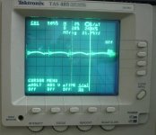
All measurements were done with a 200MHz analog tek scope, my favorite, although i have 2 others digital, they cannot catch the smallest artifacts, as the analog one does.
the attached pictures are taken while i tested a SMPS500R +-60V.
1. output ripple across +-60V output, 200mA load.
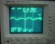
2. output ripple, 2.5A. what look like a noise, is the output ripple modulated with 100Hz (rectified mains) which create the frequency shift, absolutely normal for this topology
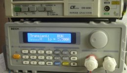
3. DC Load set on transient mode, 200mA to 2.5A step, 12.5ms each step.
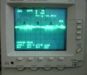
4. output voltage shots, the A portion represents 2.5A load while B represents 200mA. on the A portion the ripple previously seen in picture 2 can be saw with an amplitude of ~ 60mV pk-pk.
I can't remember when or where i saw a power supply which give as much inside details, such a parts values, characteristics, etc. i already provided enough information in the manuals so any noob would be able to replicate any power supply or build it on his knees, now i can expect to be asked to post the full schematic and pcb files, to save some time and make the job easier for those who consider that is easier to take something ready done and use-it as it is or even with commercial purpose. well, this is not a reference design, when i will do reference designs, i will post all the missing information.
I've just made some tests and took some pictures. I chose the SMPS500R +-60V output voltage. the tests were done at 200mA and 2.5A. that means 24W and 300W. why not 500W ? the DC load is rated to 300W and for higher current draw will enter in protection mode. if more tests are needed, i will do them tomorrow or next year
is too late for experiments right now.I see above some "interesting" questions, although not for for many. i will try to clarify the ones which i consider that must be clarified.
- the topology is LLC, a particular series resonant converter with lower mag. inductance.
- output voltage is adjustable within aprox. 10% range depending on model.
- first version had used a MOV. i decided to remove it in the later versions. the power supply is not to be used in any environment with heavy pouted mains supply.
- the balancing resistors are there, R1 and R2, just need to follow the schematic careful, and understand what you see.
- the bias winding supply the controller ic, which draw about 5-10mA at 12V. that's a lot, compared with the power supply power rating
to give you a hint, 1% of secondary wingdings leakage inductance difference would lead to much much more flux unbalance in the transformer. 90% or more of the commercial LLC converters are using a single winding for bias. - the caps used might differ from one batch to another, but all are within specs, rated ripple current and voltage. moreover, i do reserve the right to make changes both in schematic or parts values to attain better performances.
All measurements were done with a 200MHz analog tek scope, my favorite, although i have 2 others digital, they cannot catch the smallest artifacts, as the analog one does.
the attached pictures are taken while i tested a SMPS500R +-60V.
1. output ripple across +-60V output, 200mA load.
2. output ripple, 2.5A. what look like a noise, is the output ripple modulated with 100Hz (rectified mains) which create the frequency shift, absolutely normal for this topology
3. DC Load set on transient mode, 200mA to 2.5A step, 12.5ms each step.
4. output voltage shots, the A portion represents 2.5A load while B represents 200mA. on the A portion the ripple previously seen in picture 2 can be saw with an amplitude of ~ 60mV pk-pk.
I can't remember when or where i saw a power supply which give as much inside details, such a parts values, characteristics, etc. i already provided enough information in the manuals so any noob would be able to replicate any power supply or build it on his knees, now i can expect to be asked to post the full schematic and pcb files, to save some time and make the job easier for those who consider that is easier to take something ready done and use-it as it is or even with commercial purpose. well, this is not a reference design, when i will do reference designs, i will post all the missing information.
Attachments
Last edited:
these days the class D amplifiers also have switching noise.......the noise you speak of gets filtered out.
By the way what i say about the electrolytics applies to ALL other SMPS companies who do this kind of non-PFC smps, not just connecxelectronic......also my comments about voltage mode etc, etc, Connexelectronic is not being singled out, these points tend to apply to all others too....but from above, the transient response looks very good......i am wondering now if a sectioned bobbin was used there because they tend to give more gain...............anyway, back to the op's question of what power level he needs.......it depends on what type of amplifier you supply
By the way what i say about the electrolytics applies to ALL other SMPS companies who do this kind of non-PFC smps, not just connecxelectronic......also my comments about voltage mode etc, etc, Connexelectronic is not being singled out, these points tend to apply to all others too....but from above, the transient response looks very good......i am wondering now if a sectioned bobbin was used there because they tend to give more gain...............anyway, back to the op's question of what power level he needs.......it depends on what type of amplifier you supply
Last edited:
another point for the SMPS500 would be line regulation.
Eg, as the mains varies over 98-127VAC, what, if any, is the variation in V(out).
LLC resonant converters (not just the ones by Connexelectronic) are known for having poor line regulation.
I appreciate that for many diy'ers this wont be relevant as there mains will be constant.
Also, i see no external artificial "leakage" inductor, so smps500 must be using a leakage term in the transformer.........it is obtained by reducing the coupling between primary and secondary.....this creates interesting points such as, with such reduced coupling, can you be sure that both halves of the split rail output are coupled into the primary with the same coupling coefficient?
And what is cross regulation like with each half of the split rail output?.........if a long bass note is played do we start to see the plus and minus rails drift from their desired value?
i cannot see how one can easily get a multi output supply with an LLC resonant converter since multi output supplies require good coupling in the transformer of all windings......the modus operandi of an LLC resonant converter deliberately requires poor coupling between primary and secondary....so cross regulation figures would be nice to see.
this isnt a criticism of connexelectronic........since virtually all other manufacturers use this same smps500 type configuration too....so it applies to them too.......but they are not nice enough to come here and speak with us, whereas connexelectronic have shown their openness and quality by coming to talk here...well done to them.....they must as i say go to the top of the list of quality
Last edited:
I can offer SMPS design consultance
Microsim, can you do me a favor and read again carefully the manual ?
The power supply is designed to deliver 500W+ for short time, and peak power over 650W. the semiconductors and transformer are able to sustain the max. power but it is not thermally designed to sustain the max. power for indefinite time. none of the available power supplies for audio are. with a crest factor of 3 or more, is a total waste, and would cost much more to be built for long term max. power.
The capacitors which you mention would not blow up at 170.0001W or more, please redo the math. also, the crest factor, (read again 2 rows above) and the average power with music signal is not more than 150W. i measured this already.
for some 110V boars i have used 1200uF/200V SMQ series rated at 3.5A each.
let me explain you what will happen if the rated ripple current of the caps is exceeded.
first, they will not blow-up instantly as you expect. the ripple current will increase the temperature due to resistive losses. the series resisance for this caps is max. 300mR for 820uF and max. 200mR for 1200uF. so, let;s make a simple math. i take 5A. 5*5*0.2=5W that's a lot of power to be dissipated, and will increase the capacitor temperature if is continuous and not just peak. this will have a negative effect on the lifespan. we all know that the caps lifetime (usually 2000-5000hours) is stated at the RIPPLE CURRENT AND MAX. WORKING TEMPERATURE (85* or 105* depending on the model). we also know that roughly each 5* temperature drop from the max. temp. will double the lifespan of the cap. so if we assume that the cap can will reach 50*C in normal operation, and the armature will reach 60*C, we have a 25 or 45*C temp difference. that's a 32 or 512 times lifespan. and with the increased ripple current.
i don't want to go too deep in details, but a simplified formula for temperature rise of the cap in *C is (Ploss/area)^0.85 where Ploss is the dissipated power, see above, and area is the capacitor total outher area expressed in sq. cm. the thermal conductivity from the cap to PCB is neglected, and usually it helps to reduce the temp, if the pcb was properly designed.
You stated few months ago that the caps from the resonant tank of SMPS2000R are undersized, and for sure will blow. i don't want to search the post unless you insist. there are 4 caps in parallel, each rated at 19A peak, so total is 76A. the peak resonant current is ~ 17A. i will search the caps datasheet if need.
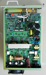
Using your algo to calculate the ripple current of the mains filter caps, the power supply from the attachment is a telecom / industrial smps rated at 1200W continuous and 1440W max. power. mains supply voltage range is 187 -254V. there is no PFC, the estimated worst case efficiency at min. input voltage and max. load is 82-85%. the caps are 3 pcs 470uF 450V SMH series, rated at 2.53A each. please calculate after how many hours (or minutes) the caps will fail. i have one of these power supplies, it is 10 years old, and i bought it from scrap, in perfect working condition, and i believe it had a hard life, since i spent almost 2 hours to clean the 1 finger thick dust inside.
If is not criticism, could you please decide if they are good or crap, reading your posts i see that you contradict yourself even within a single post, no need to count few more.
I understand that your task is to design and build some power supply and class D amp, after reading some other posts, one or more threads opened after each idea, or phrase read somewhere. if you're willing to learn how to design a good power supply, why dont you ask directly what you need to know instead of throwing the dead cat that everything what is not done as you would do, is wrong.
also, i don't know or care for who you're working, but i can help you with the design if you want (and pay for). but perhaps that's a very bad idea, and your superiors doesn't even know that you're in the middle (avoid to say beginning) of learning process and they would penalize you for making your homework in public. in my case, if i would start asking on forums how to do this and that when i get a task from the company where i work, i would be fired next day, possible with bad consequences. call them crazy if you want, but they cant wait till i figure out what to do, when i was hired i they cosidered that i know how to do and i will not gonna start learning while they will pay me, second, they don't want to make public what they (we) are doing before the product is released, especially in this part of the world. and no, right now i do not design power supplies only.
Microsim, can you do me a favor and read again carefully the manual ?
The power supply is designed to deliver 500W+ for short time, and peak power over 650W. the semiconductors and transformer are able to sustain the max. power but it is not thermally designed to sustain the max. power for indefinite time. none of the available power supplies for audio are. with a crest factor of 3 or more, is a total waste, and would cost much more to be built for long term max. power.
The capacitors which you mention would not blow up at 170.0001W or more, please redo the math. also, the crest factor, (read again 2 rows above) and the average power with music signal is not more than 150W. i measured this already.
for some 110V boars i have used 1200uF/200V SMQ series rated at 3.5A each.
let me explain you what will happen if the rated ripple current of the caps is exceeded.
first, they will not blow-up instantly as you expect. the ripple current will increase the temperature due to resistive losses. the series resisance for this caps is max. 300mR for 820uF and max. 200mR for 1200uF. so, let;s make a simple math. i take 5A. 5*5*0.2=5W that's a lot of power to be dissipated, and will increase the capacitor temperature if is continuous and not just peak. this will have a negative effect on the lifespan. we all know that the caps lifetime (usually 2000-5000hours) is stated at the RIPPLE CURRENT AND MAX. WORKING TEMPERATURE (85* or 105* depending on the model). we also know that roughly each 5* temperature drop from the max. temp. will double the lifespan of the cap. so if we assume that the cap can will reach 50*C in normal operation, and the armature will reach 60*C, we have a 25 or 45*C temp difference. that's a 32 or 512 times lifespan. and with the increased ripple current.
i don't want to go too deep in details, but a simplified formula for temperature rise of the cap in *C is (Ploss/area)^0.85 where Ploss is the dissipated power, see above, and area is the capacitor total outher area expressed in sq. cm. the thermal conductivity from the cap to PCB is neglected, and usually it helps to reduce the temp, if the pcb was properly designed.
You stated few months ago that the caps from the resonant tank of SMPS2000R are undersized, and for sure will blow. i don't want to search the post unless you insist. there are 4 caps in parallel, each rated at 19A peak, so total is 76A. the peak resonant current is ~ 17A. i will search the caps datasheet if need.
Using your algo to calculate the ripple current of the mains filter caps, the power supply from the attachment is a telecom / industrial smps rated at 1200W continuous and 1440W max. power. mains supply voltage range is 187 -254V. there is no PFC, the estimated worst case efficiency at min. input voltage and max. load is 82-85%. the caps are 3 pcs 470uF 450V SMH series, rated at 2.53A each. please calculate after how many hours (or minutes) the caps will fail. i have one of these power supplies, it is 10 years old, and i bought it from scrap, in perfect working condition, and i believe it had a hard life, since i spent almost 2 hours to clean the 1 finger thick dust inside.
If is not criticism, could you please decide if they are good or crap, reading your posts i see that you contradict yourself even within a single post, no need to count few more.
I understand that your task is to design and build some power supply and class D amp, after reading some other posts, one or more threads opened after each idea, or phrase read somewhere. if you're willing to learn how to design a good power supply, why dont you ask directly what you need to know instead of throwing the dead cat that everything what is not done as you would do, is wrong.
also, i don't know or care for who you're working, but i can help you with the design if you want (and pay for). but perhaps that's a very bad idea, and your superiors doesn't even know that you're in the middle (avoid to say beginning) of learning process and they would penalize you for making your homework in public. in my case, if i would start asking on forums how to do this and that when i get a task from the company where i work, i would be fired next day, possible with bad consequences. call them crazy if you want, but they cant wait till i figure out what to do, when i was hired i they cosidered that i know how to do and i will not gonna start learning while they will pay me, second, they don't want to make public what they (we) are doing before the product is released, especially in this part of the world. and no, right now i do not design power supplies only.
Attachments
Last edited:
Well i hear you say every 5*C drop in temperature gives a doubling of the lifetime of capacitor......though i always thought it was every 10*C drop in temperature gives a doubling of lifetime.
Capacitor datasheets dont really tell us much other than the ripple current that if continuous, and at the max temp, it will give the 2000 hrs (or whatever) of lifetime.
.....when we start dealing with audio loads, which have a crest factor that nobody really knows for sure.....because it depends on what kind of music the customer plays...............then we are in a situation of operation which is not dealt with by the datasheet, and we cannot for sure say what exactly the lifetime of the capacitor will be.............you can use "engineering judgement" etc etc..........but to be truthful, nobody really knows how to calculate lifetime in such cases when you have peak power durations of unknown durations for unknown duty cycles...............when the ripple currents are far above the datasheet stated values
So i agree that there are possibilities to downsize SMPS's which have a high crest factor load , but the down-sizing of components in this situation is by no means an exact science, and if we undertake it we are more or less making educated guesses.
Anyway, enough of my trying to hear the industrial secrets of Connexelectronic..........and more to the spec of the SMPS500...........
Please may i repeat the questions above concerning the line regulation over the 98-127VAC mains.?
Also, the issue of cross-regulation between the two split secondary outputs......how good is that?
Secondaries of LLC converters tend to be scrunched uo to get the leakage term..........this is not a good situation for getting the degree of coupling of each secondary into the core the same.........so are there any cross regulation issues?...including with the bias winding and the auxiliary output.............
Though i am not designing a power supply for audio.........i do know a company who is doing so (or at least , was) , and who wants it for 90-265VAC.........i am not sure why they are not just buying a smps in. I do know they are interested in the possibilities of down-sizing the SMPS (ie using smaller heatsinks, smaller caps etc) because of the predicted high crest factor.
I am afraid that in the abscence of exact information as to the exact time domain power draw of the amplifier, i was unable to offer them anything other than an SMPS which would be able to handle the maximum power continuously.....(so obviously it was an SMPS with a PFC)......Anyway, they declined my offer and i do not work for them.
Last edited:
@ eem2am
I noticed that you are good technically, but i cant see any results from your posts.
Either you tell us what you need exactly, or please show us something better that connex SMPS units.
Also many threads around for you asking about SMPS, and SMPS building.
please be specific.
I noticed that you are good technically, but i cant see any results from your posts.
Either you tell us what you need exactly, or please show us something better that connex SMPS units.
Also many threads around for you asking about SMPS, and SMPS building.
please be specific.
- Status
- This old topic is closed. If you want to reopen this topic, contact a moderator using the "Report Post" button.
- Home
- Amplifiers
- Power Supplies
- SMPS for audio.