Hi!
I'm planning to build a chipamp, with a preamp together.
The preamp would be uC controlled, with rotary encoder, LCD display, PGA2310 volume control, source selector with relays. Besides the volume control and source selection tasks, the uC would manage speaker protection and on/off pop elimination by controlling an output relay (monitoring AC, rail voltages, and output DC offsets).
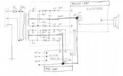
The power amplifier would be 2xLM3886 with dc servo circuit, and I planned the output relay and also the PSU all populated on the power amplifier PCB.
The two separate PSUs would have independent grounding. Both the pre- and power amplifier could have their own star-point, which are connected as shown on the drawing. (since left and right 'power' amps and also the power PSU are located on the same PCB, there is only one star-point on the power-amp board).
Please consider my drawing as a simplified one, I did not indicate all the capacitors, the snubbers, and also regulators are missing for the low-voltage PSU...
I'm asking for you suggestion about PSU wiring (grounding) and fuses.
Here are my questions:
1) Do you think this grounding is OK? Is this a good method to eliminate noise produced by uC, relays, LCD, etc.... (only the link between GND2 to SP2 has 'noisy' currents, so link between the two star-points should be clean and free of problems. Besides, no ground loop is formed.)
2) Is it OK to have only one ground star point on the power-amp board (including ground for speakers)?
3) Safety earth of IEC socket is directly connected to the chassis. But which other point has to be connected to this safety grounding point? SP1 or SP2? Which is better for safety and 'shielding'?
4) F1 is a fuse which is cumpulsory, and noone skips this. But is it neccesary to have more fuses? At which point would you insert then? If there are fuses after the power-PSU, is it worth to have them independently for left and right channels?
5) How would you put there protection for the preamp supply? Is it necessary?
Thanks for your help in advance!
Peter
I'm planning to build a chipamp, with a preamp together.
The preamp would be uC controlled, with rotary encoder, LCD display, PGA2310 volume control, source selector with relays. Besides the volume control and source selection tasks, the uC would manage speaker protection and on/off pop elimination by controlling an output relay (monitoring AC, rail voltages, and output DC offsets).
The power amplifier would be 2xLM3886 with dc servo circuit, and I planned the output relay and also the PSU all populated on the power amplifier PCB.
The two separate PSUs would have independent grounding. Both the pre- and power amplifier could have their own star-point, which are connected as shown on the drawing. (since left and right 'power' amps and also the power PSU are located on the same PCB, there is only one star-point on the power-amp board).
Please consider my drawing as a simplified one, I did not indicate all the capacitors, the snubbers, and also regulators are missing for the low-voltage PSU...
I'm asking for you suggestion about PSU wiring (grounding) and fuses.
Here are my questions:
1) Do you think this grounding is OK? Is this a good method to eliminate noise produced by uC, relays, LCD, etc.... (only the link between GND2 to SP2 has 'noisy' currents, so link between the two star-points should be clean and free of problems. Besides, no ground loop is formed.)
2) Is it OK to have only one ground star point on the power-amp board (including ground for speakers)?
3) Safety earth of IEC socket is directly connected to the chassis. But which other point has to be connected to this safety grounding point? SP1 or SP2? Which is better for safety and 'shielding'?
4) F1 is a fuse which is cumpulsory, and noone skips this. But is it neccesary to have more fuses? At which point would you insert then? If there are fuses after the power-PSU, is it worth to have them independently for left and right channels?
5) How would you put there protection for the preamp supply? Is it necessary?
Thanks for your help in advance!
Peter
Attachments
Andrew, thanks for taking a glance at my question!
The common signal-current return path of left and right channels is the 'ground' between the two star points (between SP1 and SP2).
I intended to have this ground line not to carry any currents of relays, uC, etc, it is there only for the signals from the preamp to the power amp. It's like connecting two separete devices together...
I have to admit that the words 'flow' and 'return' are a bit confusing for me. I hope I undestood you correctly...
Every circuit has a route.
That route Flows from the voltage source. The current travels through the wires and devices and eventually Returns to the voltage source.
That is the Flow and Return. Every "circuit" has a Flow and Return.
Identify the Flow and Return for the source equipment feeding a signal into your proposed amplifier. Are the Flow and Return pair forming a loop? Will that loop act as an aerial to pick up radiated interference?
That is why "low loop area" circuits are there, they try to attenuate the interference.
If you ignore this practice of low loop area you are opening up the probability that interfere can reduce the performance of your amplifier. Or worse, it could cripple the performance.
Flow and return are indeed a bit nebulous, as we are talking an AC circuit. Just as Andrew says, electrons need to find their way back to their source. That source alternates between the "signal" and "return" alternatively. Otherwise, no current and that means no work. Signal or return or really more of convenience terms so we know what each other is talking about. The signal is actually the difference between the assigned signal lead and an arbitrary reference, we call ground or return.
Where the effects of low loop area are important is that because "ground" is a misnomer, it is just part of the circuit with parastatic elements and exposed to the environment just like the "signal" half of the circuit.
Entire textbooks have been written on this. To really get complicated, you need to realize that DC ground may not be the same as AC ground, as AC may capacitance or inductive coupled through other paths. I remember a piece of '70s era computer equipment that was 80pF between the chassis and a computer room floor. We could get an AC HF return path through the metal of the raised floor!
Now I understand what you meant... The loop area of signal wires will be kept as small as possible (that's why I've drawn signal wires and ground between the star points close to each other).
The separated grounding in the PSU section is intended to eliminate the huge loop, and also current flow on the 'signal return'.
Actually my original questions were mainly about safety (protective) earthing, and fuses, but of course any kind of suggestions are appreciated...!")
Anyway, it's good to keep in mind, that loop areas have to be reduced, both for signal paths and power feed...
The separated grounding in the PSU section is intended to eliminate the huge loop, and also current flow on the 'signal return'.
Actually my original questions were mainly about safety (protective) earthing, and fuses, but of course any kind of suggestions are appreciated...!
Anyway, it's good to keep in mind, that loop areas have to be reduced, both for signal paths and power feed...
On to your PS design:
I would place fuses between the transformer and bridges.
You don't say what kind of rectifiers. If standard, I would put in snubber caps across each of them. I also usually put a snubber across the power switch and for good measures, I usually pot a MOV in there.
I get a bit hyper about what I call tri-star. Not only do I use star topology for the ground wireing, but again for each power leg.
I tend to use stranded wire with relativity fine strands.
Consider what caps you are using, and their ESR. We used to always say bigger is better, but energy storage is only half of the story, they are filters, so low ESR may have more to do with sonic detail than how big they are.
Being old school, I also like bleeder resistors across the caps.
I tend to insulate the case and not have earth grounded low power equipment. I AC couple the case to common for RF. This assumes a polarized plug and your house being wired correctly.
Low ESR caps and a nice oversize transformer can cause pretty big inrush, so don't scrimp on rectifier current.
Don't forget really good low ESR caps (film) as close to the module leads as possible.
I am just now ordering parts to see if tall the hype about HEXFREDs is justified. I have two target amps so I can do before and after analysis with a spectrum analyzer. Half of me says the physics make sense, the other half says snubbers are cheap and good filter caps should make the difference moot, or "mute" for any punsters out there.
- Status
- This old topic is closed. If you want to reopen this topic, contact a moderator using the "Report Post" button.
- Home
- Amplifiers
- Power Supplies
- PSU for preamp and chipamp