Hello,
Sorry if this is in the wrong forum. I am looking to build a balanced power supply unit, much like this one:
Projects update and iformation page
Unfortunately, there is no schematic, and I am not sure I just want to go by eye. It looks like it is within my skill set, and just need to take the proper steps and work carefully as one should when working with 120v power. Anyone tried to build this or have a schematic? If not, can anyone suggest a similar alternative?
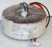
The Cheapskate calls for a 60-0-60 transformer from P/E. I read that the 60-0-60 115v unit is actually 62-0-62 at 120v. Is this accurate? If so, can I use the transformer pictured? Based on the APC site, and the wattage of my components (minus power amp - goes direct to my outlet), I can get away with a unit that is 500VA. I even factored in my TV and may just keep that on a separate outlet anyways. These transformers in the photo are 572VA, 62-0-62 at 120V and they only cost $20 locally. Would it be useable to make a small balanced power supply? Thanks
Sorry if this is in the wrong forum. I am looking to build a balanced power supply unit, much like this one:
Projects update and iformation page
Unfortunately, there is no schematic, and I am not sure I just want to go by eye. It looks like it is within my skill set, and just need to take the proper steps and work carefully as one should when working with 120v power. Anyone tried to build this or have a schematic? If not, can anyone suggest a similar alternative?
The Cheapskate calls for a 60-0-60 transformer from P/E. I read that the 60-0-60 115v unit is actually 62-0-62 at 120v. Is this accurate? If so, can I use the transformer pictured? Based on the APC site, and the wattage of my components (minus power amp - goes direct to my outlet), I can get away with a unit that is 500VA. I even factored in my TV and may just keep that on a separate outlet anyways. These transformers in the photo are 572VA, 62-0-62 at 120V and they only cost $20 locally. Would it be useable to make a small balanced power supply? Thanks
Attachments
schematic is a lot of work. ") Follow this order
Follow this order
AC hot input, modular IEC socket with line filter in it (optional, mentioned but not implemented on linked project), OR fuse next then line filter block mounted inside (also optional), NTC thermistor, transformer primary #1 lead. AC neutral input, modular IEC or line filter block (again, optional), transformer primary #2 lead. AC ground input, chassis ground bolt/screw.
Transformer secondary 2 x 60VAC leads split into individual runs to each filter block then to outlets' hot and neutral, across outlet hot and neutral is <=1uF line rated film capacitor. Filter block body is grounded by attachment to metal chassis, outlet ground goes to filter block ground terminal.
Transformer center tap, chassis ground (along with AC input ground).
I take no responsibility for inaccuracies above, but that's what it looks like to me. I might've left out something, usually it's easier to think while doing it, you see wires sticking out begging to be done something with...
A slow blow fuse rated slightly higher amperage than the transformer could be put in series on one of the transformer's secondary winding leads, but it's definitely not "user friendly" to the extent that anyone who didn't know the boxes' limitations could plug anything into it.
Follow this orderAC hot input, modular IEC socket with line filter in it (optional, mentioned but not implemented on linked project), OR fuse next then line filter block mounted inside (also optional), NTC thermistor, transformer primary #1 lead. AC neutral input, modular IEC or line filter block (again, optional), transformer primary #2 lead. AC ground input, chassis ground bolt/screw.
Transformer secondary 2 x 60VAC leads split into individual runs to each filter block then to outlets' hot and neutral, across outlet hot and neutral is <=1uF line rated film capacitor. Filter block body is grounded by attachment to metal chassis, outlet ground goes to filter block ground terminal.
Transformer center tap, chassis ground (along with AC input ground).
I take no responsibility for inaccuracies above, but that's what it looks like to me. I might've left out something, usually it's easier to think while doing it, you see wires sticking out begging to be done something with...
There are some safety issues with this project!
Like multiple 20 Amp receptacles connected to the output of a 5 Amp transformer.
A slow blow fuse rated slightly higher amperage than the transformer could be put in series on one of the transformer's secondary winding leads, but it's definitely not "user friendly" to the extent that anyone who didn't know the boxes' limitations could plug anything into it.
Last edited:
TNT carries a lot of info on PSU
hifi on TNT-Audio - online review for HiFi and Music
There is also a diy site that shows a balanced power supply. Could it be Risch?
To minimise the source impedance of your mains supply, I would suggest a much larger transformer. Maybe 1kVA.
Does the USA have site transformers for portable power tools?
In the UK they are 240:55-0-55Vac. These safety transformers are available from a few hundred VA to tens of kVA. Second hand ones are usually a bit cheaper.
Last edited:
Andrew, I don't recall ever seeing portable transformers in the US big-box supply stores.
But lot's of surplus power transformers are available. Two shops in my city have surplus transformers. Decoding the name plate specs. might take some skill.
Transformers
:: HGR Industrial Surplus - We Buy & Sell Everything! ::
But lot's of surplus power transformers are available. Two shops in my city have surplus transformers. Decoding the name plate specs. might take some skill.
Transformers
:: HGR Industrial Surplus - We Buy & Sell Everything! ::
> can I use the transformer pictured?
62-0-62 (124V) at 2.5A is 310VA.
Yes, it also says "572VA". I can not bring up Amipo's site to see the full specs.
> multiple 20 Amp receptacles connected to the output of a 5 Amp transformer.
Yes. This might be OK until someone plugs-in the vacuum cleaner.... "special purpose" outlets MUST be kept out of reach of general purpose users/plugs.
Also fuse the primary to no more than the rating.
A core this size heats slowly in overload, but will heat and release a LOT of stinky smoke. There is some possibility for release of flame or stray electricity (fire, shock). The junction box illustrated is good, but probably rated to contain hot wire-splices, not big transformers which may release a lot more trouble when provoked.
> source impedance of your mains supply
Excellent point. Your consumption over a cycle may average less than 500 Watts but these type of power supplies are liable to pull a big spike less than 10% of the time. When mixed with a lot of lights and such, this may be neglected; when all concentrated together the spikes will really sag the source. (This is an issue with non-incandescent film-lights on portable generators.)
US/Can wall-outlet sags less than 2% at 120V 20Amps, less than 0.12 ohms impedance.
A 500VA transfo may have 5% sag on resistive load. At 120V 5A this is more like 1.2 Ohms.
If a "2 Amp" device really pulls 10 Amp spikes, that's a 12V drop just when it (and most of your other gear) needs it most.
Because of the square-term in IR^2, such spikes make a lot more heat than the averaged VA might suggest.
The toroid may do better than 5%. Or may not.
A particular point is that circuit breakers are designed to trip quickly when 120V is shunted by #12 wire. If instead you have 60V gone astray through #16 or the thinner stuff in transfo windings, the cellar breaker is not sure to trip expeditiously.
OTOH this is not SO very different from our 400 Watt audio-amp projects. A box, a double handful of iron, a 3AG fuse. The only big difference is that you can't plug a vacuum cleaner into speaker outlets (and most audio amps would shut-down or quietly fry).
I really dislike this idea of mounting receptacles in knockouts. It aint right. Use receptacle covers on device boxes, nippled to the junction box mis-applied as a transformer housing.
It's not just the schematic. The short-term energy on a "120V 20A" line can be 120,000 Watts!! I've been too close to a slightly larger accident and I don't want to be there. You can pull 3,600 Watts for a frighteningly long time before the breaker trips. I've seen the damage when this happens too often.
> Does the USA have site transformers for portable power tools?
No. That is strictly a BS thing. I have not seen that technology anywhere outside UK-dominated electrical markets.
Under US/Can NEC wording, "balanced 120V" is a very grey area. There is a core assumption that all circuits will be grounded (with very narrow exemptions). There is an unsaid assumption that ground will be on one line. There is no formal guidance for CT 120V. You must thread a maze through Sec 250 and also "Derived services" and "transformer vaults".
FWIW: our core power _IS_ grounded CT, but CT on a 240V winding.
Here in Maine we stand in the mud with 120V in our hands. Recent handheld tools are all-plastic, but I have all-metal grinder and saws which will never die (but may have killed former owners). Any work-site big enough to fall under OSHA worker-safety rules is supposed to have GFI protection on all lines. A distribution box with GFI, 6 outlets, and mud-feet is standard in big-box building supply stores. I've never seen one on-site. 120V is not always fatal. Your raw 240V is a little more fatal and your BS did the right thing by designing a very special power scheme for construction sites.
It just occurred to me.
The USA domestic supply is already balanced.
Your transformer outside is a centre tapped 110+110Vac.
They bring in one phase and connect it as 110-0Vac for normal appliances.
In some "heavy duty" rooms they bring in both phases to give a high power 220Vac supply.
This 220Vac supply is actually 110-0-110Vac. It is balanced and the 0 is Neutral.
Now, back at the distribution board. Are your domestic system always earthed here? Does the Earth and Neutral always connect here?
It would appear that all that might be required is isolation.
How would this best be achieved?
From Equi=tech faqs
Is this telling us that they have chosen a bigger core and thus running the core at less flux?
Or is there more to it?
Section 3 dealing with peak current demands and the advantages of using their Q transformers.What is a “Q” transformer?
“Q” transformers were developed by Equi=Tech engineers to solve several problems common in typical toroid transformers. There are 3 areas where conventional toroid transformers miss the mark in performance.
1. Acoustical noise. Most of the time, standard toroid transformers will perform quietly and emit almost no audible noise. However, in residences and in other areas with poor utility power, the transformers react physically to excessive current distortion. The more distortion, the more the transformer vibrates. This dissipation of reactive energy, while being very helpful to equipment power supplies, can still be quite annoying. It is interesting to note that this problem has been worsening since the mid-90s. Our customer support technicians report acoustical noise problems in as many as 2 out of 5 residential locations whereas in the early 90s, the frequency of reported noise problems was perhaps 2 out of 50 locations. This recent decline in power quality is due to the increased use of microwave ovens, personal computers, HDTVs with large switching power supplies, home security systems, lighting controllers and other types of home theater equipment, especially digital audio and video components. All of these types of loads produce excessive current distortion which distorts the power in an entire neighborhood. The problem continues to worsen. Commercial users, though somewhat protected are not immune to this problem either. Most states have minimum power quality standards and tarrifs for commercial occupancies which may alleviate the problem at times, but none at all for residential neighborhoods. “Q” transformers are immune to current distortion and operate much more quietly than any other type transformer.
2. Inrush current -- the "achilles heel" of toroid transformers. While toroids are the most efficient of all transformer designs, their comparatively light core saturates very quickly which means that there will often be a large current surge when first turned on. This causes nuisance circuit breaker tripping. Many manufacturers of balanced power products use soft start relays to alleviate the inrush current problem inherent in typical toroid transformers. That is a band aid solution intended to compensate for an inexpensive transformer design. Furthermore, more parts means more that can go wrong and sooner or later it does. Q transformers handle the inrush current problem passively and need no soft-start circuits. The greater mass of the “Q” transformer as well as the type of core material and winding specifications used eliminates the need for any soft start device.
3. Slow or lagging current response. "Q" transformers respond to sudden peak current demands more quickly than any other type of transformer. Power conditioners and filter networks of all kinds choke current which adversely affects the performance of electronic components with large peak current transient demands such as power amplifiers. When current response is slow, the first noticeable change is loss of low frequency definition. Bass begins to break up and sound bloated. Deep bass resolution gives way to “boominess.” Q transformers are engineered to operate with a much lower magnetic flux density which provides more headroom for large current transients. The difference Q transformers provide in bass performance is something truly remarkable to experience.
Is this telling us that they have chosen a bigger core and thus running the core at less flux?
Or is there more to it?
> The USA domestic supply is already balanced.
At the pole and at the cooker.
As you note, this is split at pole and in fusebox.
All our little stuff runs 120V UN-balanced. (Same as you run 240V un-balanced, even to cooker.)
One side of the lamp-socket is live, the other is negligible voltage to dirt or faucet.
> at the distribution board. Are your domestic system always earthed here? Does the Earth and Neutral always connect here?
"Always" is a strong word. Ground wires are often omitted or neglected (busted).
Yes, it is Required to bond incoming CT to dirt.
(I've been reading my history and this point was not well established in early 1915, but was ernestly discussed. Within a few years distribution and building wires were required to be grounded, though practice lags regulation.)
> all that might be required is isolation
"Separately Derived Services" covers this. I've read it; don't have it at hand and it is dangerous to quote faulty memory cells. But as a general thing, on-premise "floating" sources such as secondary windings and generators must be grounded. Very limited exceptions for hospitals and steel-mills.
In fact as a general thing NEC requires ALL METAL on the premises to be bonded to incoming CT and to dirt. Even aluminum siding. Exception is the insides of Double Insulated tools.
However... the exact location of the ground on the separately derived service is not specified. In most cases there is no choice: one end. However a CT is not specifically forbidden. Therefore a 60-0-60 source is not illegal under NEC. If permanently installed, it is up to the local Inspector how to call it. If loose, your homeowner's insurance (and some city codes) would like it to be UL-approved, though they will never know until a fire or death.
And there is a case where 60-0-60 voltage combined with another "too clever" line-side scheme burned-up a very expensive audio system. Basically since 60-0-60 is so unusual, other designers don't even consider it.
Hmmmm... now we have a Global Market, much of our stuff can eat 240V. We DO have Balanced 240V. We could carefully change all our plugs to the 240V 15A Hubbell, add a 15A double-pole breaker to the fusebox, 15A 240V outlets near the equipment. We must NOT plug a CD deck into the dryer outlet, because the 40A breaker and fat wire could easily start a fire in a line-cord sized to blow 20A fuses, we need the low-Amps breaker and a dedicated circuit.
--------
The quoted Section 3 appears to have been garbled between the technical guru and the marketing department.
Here is the link to an alternative you want to consider. While more expensive than that "cheapskate" project, it is far less expensive than most other commercially engineered units to which I'm aware.
Transcendent Sound Power Supply
Noel
Transcendent Sound Power Supply
Noel
Last edited:
- Status
- This old topic is closed. If you want to reopen this topic, contact a moderator using the "Report Post" button.
- Home
- Amplifiers
- Power Supplies
- Cheapskate Balanced Power Supply