Hi All
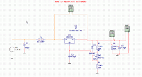
I just want to now what you think about this one, it simulates good, 10 mA to 1 amp just 100 mv difference in output.
it is a shunt coupled to a source follower, I need it for a hybride who use white follower, on differential supply dc coupled to mosfets.
I have now test it in amp, and he is so quied as a astronaut on the moon, deep black.
for the shunt mosfet you can also use a bjt npn with some changes on his base resistors, but I think mosfets are better, in simulations that is maar in my amp it does good job.
Attachments
Yep. Pretty classic design. I tried that as part of my quest for a high-voltage regulator. I found it inadequate for use in my 300B SET amp for a number of reasons. The pass device would blow on start-up due to SOA violations, the ripple rejection was mediocre, and the output voltage varied quite a bit with temperature. I eventually ended up designing a floating high-voltage regulator.
With your relatively low voltages (125 V input), you do have the benefit of being able to choose components that offer more gain. Having access to low-voltage electrolytics so you can get a decent amount of cap in a small package works in your favor as well. Specifically, the C4-R4 time constant in your circuit (main ripple rejection filter) works well with a sizable cap.
Obviously, the circuit works in your application. Good work... Just sayin' that it's hard to scale it up to higher voltages.
~Tom
Yep. Pretty classic design. I tried that as part of my quest for a high-voltage regulator. I found it inadequate for use in my 300B SET amp for a number of reasons. The pass device would blow on start-up due to SOA violations, the ripple rejection was mediocre, and the output voltage varied quite a bit with temperature. I eventually ended up designing a floating high-voltage regulator.
With your relatively low voltages (125 V input), you do have the benefit of being able to choose components that offer more gain. Having access to low-voltage electrolytics so you can get a decent amount of cap in a small package works in your favor as well. Specifically, the C4-R4 time constant in your circuit (main ripple rejection filter) works well with a sizable cap.
Obviously, the circuit works in your application. Good work... Just sayin' that it's hard to scale it up to higher voltages.
~Tom
For very high voltages there are always limitations, but I have need only 2 x 110 volt for white follower in hybride, and it simulates very nice, I have to say that in these days there are a lot very high bjt and mosfets, shunt it with a zener can protect it when startup, but has some danger in case the zener fails.
Yes tube supply is always a challence, but with the modern fets these days we can make good regulators.
classic design. mosfets are better than the transistors because they keep the power supply low in impedance.
Than bipolar junction transistors I assume you mean?
This is incorrect because BJTs have higher transconductance than MOSFETs do, at comparable operating conditions.
This doesn't matter much, because the circuit shows a big fat 22uF crushing the loop response. The output impedance of this regulator will be approximately 1/Gm of Q1, which will be in the 10s of ohms range most likely.
If R4 and C4 were removed and a small compensation capacitor (or R+C) placed across R2, and the values adjusted until critically damped transient response is obtained, you will have the lowest possible output impedance and highest PSRR. I would guess Zo will be in the miliohms, especially with BJTs, while PSRR will be >40dB.
Further improvement can be made by reducing the bias current supplied from R3; 100k or even 1M will suffice here, at some expense to high frequency response (which is easily compensated for with a customary filter capacitor on the output). This also relaxes the operating point for BJTs, which are often 2nd breakdown limited at these voltages and higher.
As a final step, the error amplifier can be changed from a single transistor to a differential pair, at the expense of one small transistor; this will essentially transform the tempco from an obvious Vbe error down to the error of D1, which could also be replaced by a lower voltage zener (with predictable tempco), or a bandgap reference such as TL431.
Then you'll have essentially the regulator circuit I built here, with a bit higher current capacity:
An externally hosted image should be here but it was not working when we last tested it.
For that matter, this circuit will do an excellent job under the same conditions, replacing the pass transistor with a MOSFET and adjusting the current shunt resistor accordingly.
Tim
If R4 and C4 were removed and a small compensation capacitor (or R+C) placed across R2, and the values adjusted until critically damped transient response is obtained, you will have the lowest possible output impedance and highest PSRR. I would guess Zo will be in the miliohms, especially with BJTs, while PSRR will be >40dB.
There is a small capacitor (C6 = 220nF) across R2. Read somewhere else that it improves the PSRR by about 10dB?
Should there be a current limitation too ?
It is only one transistor and resistor more.
Like this:
It is only one transistor and resistor more.
Like this:
An externally hosted image should be here but it was not working when we last tested it.
I have seen on this forum a lot of regulators, also this is from electuur kilowatter mosfet amp. I did now then that the regulator 7808 did blow because of the capacitors cause short until she are charged, I did use zeners to protect and this did work nicely.
this regulator TL783 is a nice one for a floating supply, see the link.
http://www.ti.com/lit/ds/slvs036m/slvs036m.pdf
this regulator TL783 is a nice one for a floating supply, see the link.
http://www.ti.com/lit/ds/slvs036m/slvs036m.pdf
Attachments
There is a small capacitor (C6 = 220nF) across R2. Read somewhere else that it improves the PSRR by about 10dB?
Oh, there it is. It will improve AC midband response by approximately the voltage divider ratio (270k into 20k, a bit over 20dB), if the loop were able to function (which it can't, since R4-C4 is several decades slower).
A resistor in series with C4 may be necessary to limit the amount of AC loop gain; too much and it can be unstable. This is more likely with more gain stages (less phase margin).
Tim
Than bipolar junction transistors I assume you mean?
This is incorrect because BJTs have higher transconductance than MOSFETs do, at comparable operating conditions.
This doesn't matter much, because the circuit shows a big fat 22uF crushing the loop response. The output impedance of this regulator will be approximately 1/Gm of Q1, which will be in the 10s of ohms range most likely.
If R4 and C4 were removed and a small compensation capacitor (or R+C) placed across R2, and the values adjusted until critically damped transient response is obtained, you will have the lowest possible output impedance and highest PSRR. I would guess Zo will be in the miliohms, especially with BJTs, while PSRR will be >40dB.
Further improvement can be made by reducing the bias current supplied from R3; 100k or even 1M will suffice here, at some expense to high frequency response (which is easily compensated for with a customary filter capacitor on the output). This also relaxes the operating point for BJTs, which are often 2nd breakdown limited at these voltages and higher.
As a final step, the error amplifier can be changed from a single transistor to a differential pair, at the expense of one small transistor; this will essentially transform the tempco from an obvious Vbe error down to the error of D1, which could also be replaced by a lower voltage zener (with predictable tempco), or a bandgap reference such as TL431.
Then you'll have essentially the regulator circuit I built here, with a bit higher current capacity:
An externally hosted image should be here but it was not working when we last tested it.
For that matter, this circuit will do an excellent job under the same conditions, replacing the pass transistor with a MOSFET and adjusting the current shunt resistor accordingly.
Tim
Looks nice but I need only low current q50 mA max, but I will try your for a test, I have also need a negatieve one because the white follower has differential supply, there is much on the internet about regulators, it seems complicated or maybe whe are never satisfy ;-).
I dont need a mosfet pass transistor persee, a bjt will do, oly I have a lot of high voltage mosfets here so I try first.
This moment the amps works with two gyrators in the supply, the ripple in the loudspeakers are now gone, it is deep black.
thanks all.
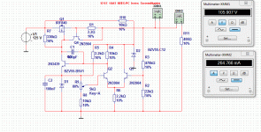
I have now do 2 things, one is a normally lm317 floating and protected with a fuse and transient diode of some amps, it works in simulation en is simple, with 80 db riple rejection .
or the one from post 11 I have done with a mosfet, I think that a normally LM317 is for me just fine and simple, maybe remove the transient diode and use a darlington npn for input as a current limiter, can simple with a zener. even a thyristor acros the lm317 can work together with a fuse.
or the one from post 11 I have done with a mosfet, I think that a normally LM317 is for me just fine and simple, maybe remove the transient diode and use a darlington npn for input as a current limiter, can simple with a zener. even a thyristor acros the lm317 can work together with a fuse.
Attachments
These regulators are nominally a bit more complex, as they use three transistors, but they remain inexpensive and have decent performances considering their cost/complexity:
http://www.diyaudio.com/forums/power-supplies/198986-simple-hv-series-regulators.html
Another route is to use complementary transistors.
This example is based on a P channel ballast, but if there are no grounding issues, polarities could be swapped (bypassing could be added to improve AC performance):
Attachments
Well these I going to use, I go make a pcb for them. it will a supply contents of plus minus 110 volt, and one 300 volt for the hybride amplifier.
I have test the one with lm317 and have try to kill it but it is quite good, it is very good protected, I have afcourse relative low voltage this counts also, I here here about 600 volt and more, there are transient diodes who can protect mosfets and transistors when power up and cause trouble with electrolitic capacitor who has to be charged, and thus see a short for a short time, here these diodes can help?
Transient Voltage Suppression, TVS Diodes, Automotive Circuit Protection - Littelfuse.com
Attachments
Well these I going to use, I go make a pcb for them. it will a supply contents of plus minus 110 volt, and one 300 volt for the hybride amplifier.
I have test the one with lm317 and have try to kill it but it is quite good, it is very good protected, I have afcourse relative low voltage this counts also, I here here about 600 volt and more, there are transient diodes who can protect mosfets and transistors when power up and cause trouble with electrolitic capacitor who has to be charged, and thus see a short for a short time, here these diodes can help?
Transient Voltage Suppression, TVS Diodes, Automotive Circuit Protection - Littelfuse.com
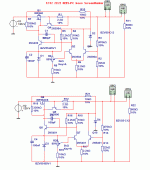
the transistors in differential has to be 3906 and not 5401 but did simulate with them, diff works on low voltage so 3906 are oke, I hope I did alright with the negative one swapping everything and also transistors for pnp to stay on same working of schematic (vbe).
I have make the schematic ready for pcb making, it is one 2x 110 volt diff supply max 150 mA and one 300 volt gyrator one with max 50 mA.
I have choosen for gyrator in this small amp supply it is not critic there with the mu follower and it's ripple is low.
I have choosen for gyrator in this small amp supply it is not critic there with the mu follower and it's ripple is low.
Attachments
I have play with ultiboard in multisim but ohhhh wat much bad components who have complete differend shapes, also the pad,s are mucho to small
and it is a lot of work to make them proper dimensions.
I go asap to eagle, or better Designspark pcb who is I think eagle.
some here experience with ultiboard? I have the dos version here, but dos is no more but that version of ultiboard was very good and easy.
and it is a lot of work to make them proper dimensions.
I go asap to eagle, or better Designspark pcb who is I think eagle.
some here experience with ultiboard? I have the dos version here, but dos is no more but that version of ultiboard was very good and easy.
- Status
- This old topic is closed. If you want to reopen this topic, contact a moderator using the "Report Post" button.
- Home
- Amplifiers
- Power Supplies
- voltage regulator with two mosfets